background image

KaCool D HC

Assembly, installation and operating instructions

40

12

Certificates

EU-Konformitätserklärung

EU Declaration of Conformity
Déclaration de Conformité CE
Deklaracja zgodno

ś

ci CE

EU prohlášení o konformite

Wir (Name des Anbieters, Anschrift):

KAMPMANN

GMBH & Co. KG

We (Supplier’s Name, Address):

Friedrich-Ebert-Str. 128-130

Nous (Nom du Fournisseur, Adresse):

49811 Lingen (Ems)

My (Nazwa Dostawcy, adres):
My (Jméno dodavatele, adresa):

erklären in alleiniger Verantwortung, dass das Produkt:

declare under sole responsibility, that the product:
déclarons sous notre seule responsabilité, que le produit:
deklarujemy z pe

ł

n

ą

 odpowiedzialno

ś

ci

ą

ż

e produkt:

deklarujeme, v

ě

domi si své odpov

ě

dnosti, že produkt:

Type, Modell, Artikel-Nr.:

KaCool D HC

525***

Type, Model, Articles No.:
Type, Modèle, N° d’article:
Typ, Model, Nr artyku

ł

u:

Typ, Model, 

Č

íslo výrobku:

auf  das  sich  diese  Erklärung  bezieht,  mit  der  /  den  folgenden  Norm(en)  oder  normativen
Dokumenten übereinstimmt:

to which this declaration relates is in conformity with the following standard(s) or other normative document(s):
auquel se réfère cette déclaration est conforme à la (aux) norme(s) ou autre(s) document(s) normatif(s):
do  którego  odnosi  si

ę

  niniejsza  deklaracja,  jest  zgodny  z  nast

ę

puj

ą

cymi  normami  lub  innymi  dokumentami

normatywnymi:
na  který  se  tato  deklarace  vztahuje,  souhlasí  s  následující(mi)  normou/normami  nebo  s  normativními
dokumenty:

DIN 1946-4

Raumlufttechnische Anlagen in Gebäuden und Räumen
des Gesundheitswesens

VDI 6022 Blatt 1

Hygieneanforderungen an raumlufttechnische Anlagen
und Geräte

DIN EN 1397

Wasserübertrager – Wasser-Luft-Ventilatorkonvektoren –
Prüfverfahren zur Leistungsfeststellung

DIN EN 55014-1; -2

Elektromagnetische Verträglichkeit

DIN EN 61000-3-2; -3-3

Elektromagnetische Verträglichkeit

Summary of Contents for 525150009020

Page 1: ...KaCool D HC Assembly installation and operating instructions Keep these instructions in a safe place for future use Issue06 21EN SAP No 1456278 ...

Page 2: ......

Page 3: ... data 12 5 Construction and function 13 5 1 Overview 13 5 2 Brief description 14 5 3 Wear parts list 14 6 Installation and wiring 15 6 1 Definition of the connection side 15 6 2 Requirements governing the installation site 15 6 3 Minimum clearances 16 6 4 Installation 16 6 4 1 Installation of basic unit 17 6 5 Installation 19 6 5 1 Connection to the pipe network 19 6 5 2 Connection of 2 way valve ...

Page 4: ...ainst reconnection 33 10 2 Maintenance Schedule 33 10 3 Maintenance work 34 10 3 1 Opening the inspection flap 34 10 3 2 Replacing the filter 34 10 3 3 Visual checks 35 10 3 4 Cleaning the condensate tray 36 10 3 5 Cleaning the float switch 37 10 3 6 Clean the inside of the unit 37 11Faults 38 11 1 Fault table 38 11 2 Start up after rectification of fault 39 12Certificates 40 Table 43 ...

Page 5: ...ns apply as do general safety provisions governing the use of the equipment Illustrations in this guide are intended to provide a basic understanding and may differ from the actual model Ongoing tests and further developments may result in small variations between the unit supplied and the instructions 1 2 Explanation of Symbols DANGER This combination of symbol and signal word indicates an immedi...

Page 6: ... use described in Chapter 2 2 6 must be observed IMPORTANT NOTE Only use the unique after completion of the complete building and system Site heating is not deemed to be correct and proper use Intended use of the unit also includes adherence to these instructions Information in accordance with EN60335 1 This unit can be used by children aged 8 years or more and also by people with reduced physical...

Page 7: ... refer to VDI 2035 Sheets 1 2 DIN EN 14336 and DIN EN 14868 with regard to the properties of the medium used to protect the equipment The following values provide further guidance The water used should be free of contamination such as suspended substances and reactive substances Water quality pH value at 20 C 8 9 Conductivity at 20 C μS cm 700 Oxygen content O2 mg l 0 1 Hardness dH 4 8 5 Sulphur i...

Page 8: ...operate the unit above electrical equipment such as switch cabinets computers or other electrical units or contacts that are not drip proof IMPORTANT NOTE Energy losses due to misuse Operating the unit with open windows or other room openings can result in significant energy losses Heating and cooling modes particularly when operating different units need to be coordinated with each other 2 3 Risk...

Page 9: ...ns i e Association of German Electricians VDE regulations DIN and EN standards DIN EN 1946 4 for compliance with advanced hygiene standards specifically for clean rooms hospitals medical practices etc VDI 6022 Ventilation and air conditioning air quality Hygiene requirements governing ventilation and air condition ing systems and units The installation operation and maintenance of this unit must c...

Page 10: ...bsite IMPORTANT NOTE 2 people are needed to transport the unit Wear personal protective clothing when transporting the unit Only lift the unit on both sides and not by the pipes valves IMPORTANT NOTE Material damage caused by incorrect transport Units being transported can drop or topple over if transported wrongly This can cause serious material damage Proceed carefully when unloading the equipme...

Page 11: ...rations and shocks IMPORTANT NOTE Under certain circumstances packages can carry storage instructions that exceed the requirements listed here Comply with these instructions accordingly 3 4 Packaging Handling packaging materials IMPORTANT NOTE Dispose of packaging materials in line with the applicable statutory requirements and local regulations IMPORTANT NOTE The packaging is also use to protect ...

Page 12: ... of basic unit mm 625 Panel width mm 580 Length of basic unit car cass mm 1250 Panel length mm 1180 Height of basic unit com plete mm 406 Weight of basic unit kg 56 5 Air volume flow m h 26 489 Internal volume of 2 pipe system l 1 5 Heat output kW 465 6301 Cooling output kW 348 3013 Sound power level dB A 29 60 ...

Page 13: ... 3 2 1 15 15 Fig 1 KaCool D HC at a glance 1 Air vents 2 Water connections 3 Actuator 4 Electrical junction box 5 Heat exchanger 6 EC radial fan 7 Filter cassette epm1 85 8 Condensate tray 9 Float switch 10 Condensate pump 11 Air baffle 12 Filter cassette epm1 55 13 Inspection cover 14 Revision flap 15 Differential pressure bellows ...

Page 14: ...ough an ePM1 55 filter and is passed through the copper aluminium heat exchanger Here the air is either heated or cooled depending on the temperature of the water in the heat exchanger Through the ePM1 85 filter the heated or cooled air is fed into the room through an 180 discharge panel 5 3 Wear parts list Figure Article Properties Suitable for Art no Spare air intake filter eP M1 55 1 no KaCool ...

Page 15: ... the ceiling is sufficiently load bearing to take the weight of the unit Technical data 12 Make sure that the unit is securely suspended standing Ensure that the airflow can circulate freely Provide adequate space for appropriately sized flow and return water connections on site Connection to the pipe network 19 There is a power supply on site Maximum electrical rating values 26 If need be provide...

Page 16: ... air discharge can cause the air to fall and lead to uncomfortable downdraughts The minimum distance between the discharge sides and the wall must be 1 4 m If several units are installed they should have a distance of 4 metres from each other There needs to be a minimum clearance of 650 mm under the unit for inspection purposes Opening dimensions in the suspended ceiling 23 819 Inch 48 031 Inch 60...

Page 17: ... NOTE Horizontal installation of units When installing the units ensure that they are completely horizontal to ensure proper operation IMPORTANT NOTE Avoid draughts Consider the occupied zone when installing suspending the units Do not expose people to the direct air flow Position the unit accordingly and adjust the air outlet if required IMPORTANT NOTE Sound insulation Provide for sound isolation...

Page 18: ...iew Plan view Left side view Fig 6 Suspension points mm Note the Venkon minimum clearances when installing the basic units Mark the dimensions and distances of the key holes on the wall or ceiling as per the drawing drill the holes and use ap propriate fixing materials to install the basic unit Once the basic unit has been levelled prevent the fixing material from coming loose ...

Page 19: ...ssels pressure relief valves and overflow valves Route condensation lines with a sufficient cross section without bends and narrow sections with a gradient to the in situ waste water pipe Allow adequate space for the air flow air inlet and outlet Additionally consider the following point with cooling mode Provide continuous vapour tight insulation on all components that carry water pipework valves...

Page 20: ...ing heating me dium With cooling units there is a danger to the user from cold temperatures and a danger to the environment from the use of glycol Put in place appropriate safety measures Remove protective caps from the supply and return With cooling mode route the pipework and valves directly over the side condensate tray accessory to drain any con densate produced on the pipes during cooling mod...

Page 21: ...HC Assembly installation and operating instructions 21 6 5 2 Connection of 2 way valve kit 1 2 3 4 4 3 Fig 8 Dimensions in mm 1 2 3 4 4 3 Fig 9 Dimensions in inches 1 Return 2 Supply 3 Supply vent 4 Return vent ...

Page 22: ...ate from the basic unit providing no adequately sized condensate pump has been fitted in accordance with DIN EN 12056 formerly DIN 1986 100 However no condensate pump is factory fitted as standard Take into account all applicable regulations such as the use of a ball trap when connecting the condensate line to the sewer system Protect the trap from drying out The suction effect of the fan on the c...

Page 23: ...vent the condensate tray from overflowing Condensate drain Drainage of condensate from the condensate pump must be along a natural gradient with an adequate cross section minimum 1 2 Increase the cross section of the line with longer condensate lines Check whether the condensate line needs to be insulated to prevent the build up of condensate along the line Do not use a rigid transition to the on ...

Page 24: ...A measured in the LNI laboratory pump operated with water not installed 20 dBA Noise level when installed at 1 m dBA measured in the Sauermann acoustic laboratory pump operated with water 27 dBA Power supply 230 V 50 60 Hz 14 W Insulation class double insulated Switching points ON 16 mm OFF 11 mm ALARM 19 mm Safety contact NC 8 A ohmic load 250 V Overheating protection switching off point 115 C au...

Page 25: ... closed Commissioning Open the cover Turn the selector dial and select the required switching point as per the Filter pressure loss table Close the cover again Filter type Starting pressure difference Pa Final pressure difference Pa epM1 55 formerly F7 15 38 ePM1 85 formerly F9 20 50 H14 Hepa 65 104 Tab 5 Filter pressure losses The final pressure differences listed apply to an operating voltage of...

Page 26: ...2 Electromechanical control 7 2 1 Connection 00 Fig 12 PCB in the electrical junction box Power supply and control The unit needs a 230 V 50 Hz power supply The fan speed of the EC fan installed can be continuously variably controlled via the 0 10 V DC Ri 100 kOhm control input The internal motor electronics detects any possible motor malfunction and automatically switches off the fan The electric...

Page 27: ...l D HC Comply with the details on cable types and cabling with due consideration of VDE 0100 Without NYM J The requisite number of wires including PE conductor is stated on the cable Cross sections are not stated as the cable length is involved in the calculation of the cross section With J Y ST Y 0 8mm Lay separately from high voltage lines If other types of cables are used they must be at least ...

Page 28: ...ate controller Type 14894x 2 Junction box 10 V T E PE N L KaCool DHC Electromechanical Unit no 1 L N KP Gnd C Uc P2 2 1 W6 2 AP 1 2 P1 3 4 4 VAL 3 Ri 100 KΩ gr ye 1 4 2 3 gr ye 1 2 Terminal box by others 1 3 4 2 4 1 4 3 2 Mains power 230 V AC Thermostat connection Motor connection Fault messages 2 3 1 4 1 2 3 4 Terminal box by others 1 gr ye 2 10 V T E PE N L KaCool DHC Electromechanical Unit no 2...

Page 29: ...hermostat connection Motor connection Fault messages Junction box NO NO NC NO NO NC Building automation system BAS 1 2 AA1 0 10 V AA1 GND Fan speed unit 1 Note the internal resistance of the unit COM DI2 Filter message discharge unit 1 Filter message discharge unit 1 Contact closed fault 3 4 DI1 DA1 Condensate alarm unit 1 Contact open fault 1 2 230V 2 gr ye 1 gr ye 1 2 2 1 2 pipe heating cooling ...

Page 30: ...lines have been properly connected Fill pipes and unit with water and bleed Check whether all bleed screws are closed Check leak tightness pressure test and visual inspection Check whether the parts carrying water have been flushed through Check whether any shut off valves fitted on site are open Check whether any electrically actuated shut off valves have been properly connected Check whether all...

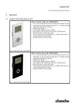
Page 31: ... room sensor 3 control inputs functions parametrisable e g window contact presence detector heating cooling switchover Parallel operation of 2 units is possible Fig 14 Climate controller type 196000148942 Climate controller black type 196000148942 For 2 and 4 pipe applications surface mounted wall mounting on a flush mounted box in visually unobtrusive design with 2 5 CD display and high quality g...

Page 32: ...s functions parametrisable e g window contact presence detector heating cooling switchover Parallel operation of 2 units is possible Fig 16 Climate controller type 196000148944 Climate controller black type 196000148944 With Modbus interface For 2 and 4 pipe applications surface mounted wall mounting on a flush mounted box in visually unobtrusive design with 2 5 CD display and high quality glass f...

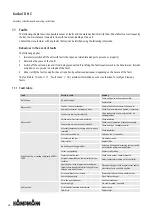
Page 33: ...for the proper and trouble free operation of the equipment If there are signs of increased wear during regular checks shorten the required maintenance intervals to the actual wear and teat Contact the manufacturer with any questions about maintenance work and intervals Interval Maintenance task Personnel As required Regular visual checks and acoustic checks for damage dirt and function User quarte...

Page 34: ...ig 17 Opening the revision flap Carefully pull the revision flap down until it comes to a stop 1 and is held by the retaining cable Loosen the revision flap from the retaining cable 2 10 3 2 Replacing the filter CAUTION Risk of injury from sharp metal housing The inner metal of the casing can have sharp edges Wear suitable protective gloves Fig 18 Removing the intake filter Remove and clean the in...

Page 35: ...internal panels Dismantle the inspection cover and the air baffle as follows for visual inspections after the revision flap has been opened Fig 20 Unscrew the wing bolts on the inspection cover Fig 21 Unscrew the wing bolts from the air baffle and remove the air baffle Fig 22 Remove the air baffle ...

Page 36: ...lements etc for soiling or deposits during maintenance and use a commercially available product to remove Then use commercially available disinfectant to disinfect the unit Clean the heat exchanger Check the heat exchanger for soiling and carefully vacuum if necessary Avoid damage to the pipework and fins 10 3 4 Cleaning the condensate tray Fig 24 Remove the condensate tray Fig 25 Clean the conden...

Page 37: ...ining panel with the float switch fitted Fig 27 Open the cover of the float switch Fig 28 Clean the float switch 10 3 6 Clean the inside of the unit Check all elements that come into contact with air internal surfaces of the unit outlet elements etc for dirt or deposits dur ing maintenance and use a commercially available product to remove ...

Page 38: ... done Check flow and return and tighten if necessary Water outlet Condensate drain outlets blocked Clean condensate outlets and check for ad equate gradient Chilled water line incorrectly insulated Check insulation Condensate drain not properly installed Check correct operation of condensate pump Check and clean condensate outlet Accessory components carrying air not properly insulated Check insul...

Page 39: ...ancing clips are removed during cleaning Fan dirty Clean dirt from fan Heat exchanger dirty Clean dirt from Heat exchanger 11 2 Start up after rectification of fault After correction of the fault carry out the following steps to re start 1 Make sure that all maintenance covers and access openings are sealed 2 Switch off the unit 3 Acknowledge fault on controller if necessary ...

Page 40: ...rticle Typ Model Nr artykułu Typ Model Číslo výrobku auf das sich diese Erklärung bezieht mit der den folgenden Norm en oder normativen Dokumenten übereinstimmt to which this declaration relates is in conformity with the following standard s or other normative document s auquel se réfère cette déclaration est conforme à la aux norme s ou autre s document s normatif s do którego odnosi się niniejsz...

Page 41: ... Zgodnie z postanowieniami Dyrektywy Odpovídající ustanovení směrnic 2014 30 EU EMV Richtlinie 2014 35 EU Niederspannungsrichtlinie Frank Bolkenius Lingen Ems den 11 06 2021 ___________________________________ Ort und Datum der Ausstellung Name und Unterschrift des Befugten Place and Date of Issue Name and Signature of authorized person Lieu et date d établissement Nom et signature de la personne ...

Page 42: ...KaCool D HC Assembly installation and operating instructions 42 ...

Page 43: ...on and operating instructions 43 Table Tab 1 Limits of operation 7 Tab 2 Operating voltage 7 Tab 3 Water quality 7 Tab 4 Technical data condensate pump 24 Tab 5 Filter pressure losses 25 Tab 6 Maximum electrical connection values 26 ...

Page 44: ...ert Str 128 130 49811 Lingen Ems T 49 591 7108 660 F 49 591 7108 173 E export kampmann de W Kampmann eu Country Contact Great Britain Kampmann UK Ltd Dial House Govett Avenue Shepperton Middlesex TW17 8AG T 44 1932 228592 F 44 1932 228949 E info kampmann co uk W Kampmann co uk 06 21 ENSAP Nr 1456278 ...

Reviews: