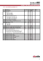
Parameter setting of valve circuit board for 0..10 V actuators
Parameters P39-P42, P95, P108, P109, P114, P115
The functions of the "Valve circuit board to activate 0..10 V actuators" is configured using the
following parameters.
The first step when configuring the 0..10 V valve circuit board is to set parameter P95 = 1!
Operation
0..10 V
activation
Min
Max Unit
P39
13 = Output No4 on the valve circuit board:
heating/cooling valve 0..10 V
13
0
18
P40
14 = Output No5 on the valve circuit board:
heating valve 0..10 V
14
0
18
P41
3 = Output No6 on the valve circuit board:
cooling requirement
3
0
18
P42
4 = Output No7 on the valve circuit board:
heating requirement
4
0
18
P95
1 = To activate the valve circuit board for 0..10 V
actuators set parameter P95 = 1.
1
0
1
P108 Reset time of PI controller to activate continuous valve
drives
Recommended reset time when using a
PI controller: Reset time=600 sec
→
Setting figure=60
60
0
255
sec. *10
P109 Neutral zone
2
255
°C / 10
P114 P-band of PI controller to activate continuous valve
drives in Cooling mode.
Recommended P-band when using a PI controller:
P-band for heating=3K
→
setting figure = 30
30
0
255
°C / 10
P115 P-band of PI controller to activate continuous valve
drives in Heating mode.
Recommended P-band when using a PI controller:
P-band for cooling=3K
→
setting figure = 30
30
0
255
°C / 10
Ka
Control
for Venkon
ASSEMBLY AND INSTALLATION INSTRUCTIONS
1.48
Venkon
48


