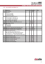
* The control automatically detects the requisite sensors at the analogue inputs B1-B3 via the DIP
switch settings. If sensors are defective or not connected, this is shown by the respective display
(L01-L03) flashing.
** Outputs No4-No7 can only be tested when using the standard valve PCB.
Hardware-related locks should be observed during the functional test (refer to the respective
wiring diagram!)
Ka
Control
for Venkon
ASSEMBLY AND INSTALLATION INSTRUCTIONS
1.48
Venkon
59
Step
Input and output
Display flashes
Display does not flash
L01*
Input B1
Sensor faulty
Sensor ok
L02*
Input B2
Sensor faulty
Sensor ok
L03*
Input B3
Sensor faulty
Sensor ok
L04
Input DI1
Contact open
Contact closed
L05
Input DI2
Contact open
Contact closed
L06
Input DI3
Contact open
Contact closed
L07
Input DI4
Contact open
Contact closed
L08
Input DI5
Contact open
Contact closed
L09
No1
--
Fan stage 1 enabled
L10
No2
--
Fan stage 2 enabled
L11
No3
--
Fan stage 3 enabled
L12**
No4
--
Power connected
L13**
No5
--
Power connected
L14**
No6
--
Relay switching
L15**
No7
--
Relay switching


