45
KaCool D
02.02.2017
Installation and Connection
Control overview
EC fans, KaControl
Accessories: Clip on temperature sensors
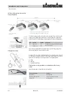
The clip-on sensors can be
fi
tted to the
fl
ow pipe
(heating/cooling) using a tension strap. The temperature
sensor and tension strap form one unit to ensure a simple
installation.
To connect the electrical connection cables
(cable length = 3 m), open the control unit, insert the cables
and connect them according to the wiring diagram.
Clip-on temperature sensors
DANGER!
Disconnect the KaCool from the mains power
supply when undertaking all electrical work..
Installation: Operating unit
KaController terminals
DIP switch setting
KaController
DIP switch no. 1:
ON
DIP switch no. 2:
OFF
Installation/Dismantling
Wiring
Connect the KaController to the nearest KaCool according
to the wiring diagram. The maximum BUS length between
the KaController and KaCool is 30 m.
By connecting a KaController, the respective KaCool
automatically becomes the master unit in the control circuit.
DIP switch setting
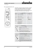
The DIP switches on the rear of the KaController
must be set according to the illustration shown opposite:
DIP switch no. 1:
ON
DIP switch no. 2:
OFF
DANGER!
Disconnect the KaCool from the mains power
supply when undertaking "all" electrical work!
The KaCool KaControl must also be disconnected
from the mains power supply when connecting the
BUS cables.


