KaCool D
02.02.2017
48
Installation and Connection
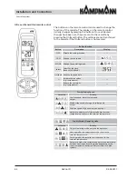
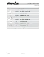
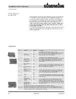
Control overview
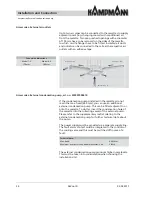
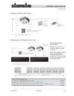
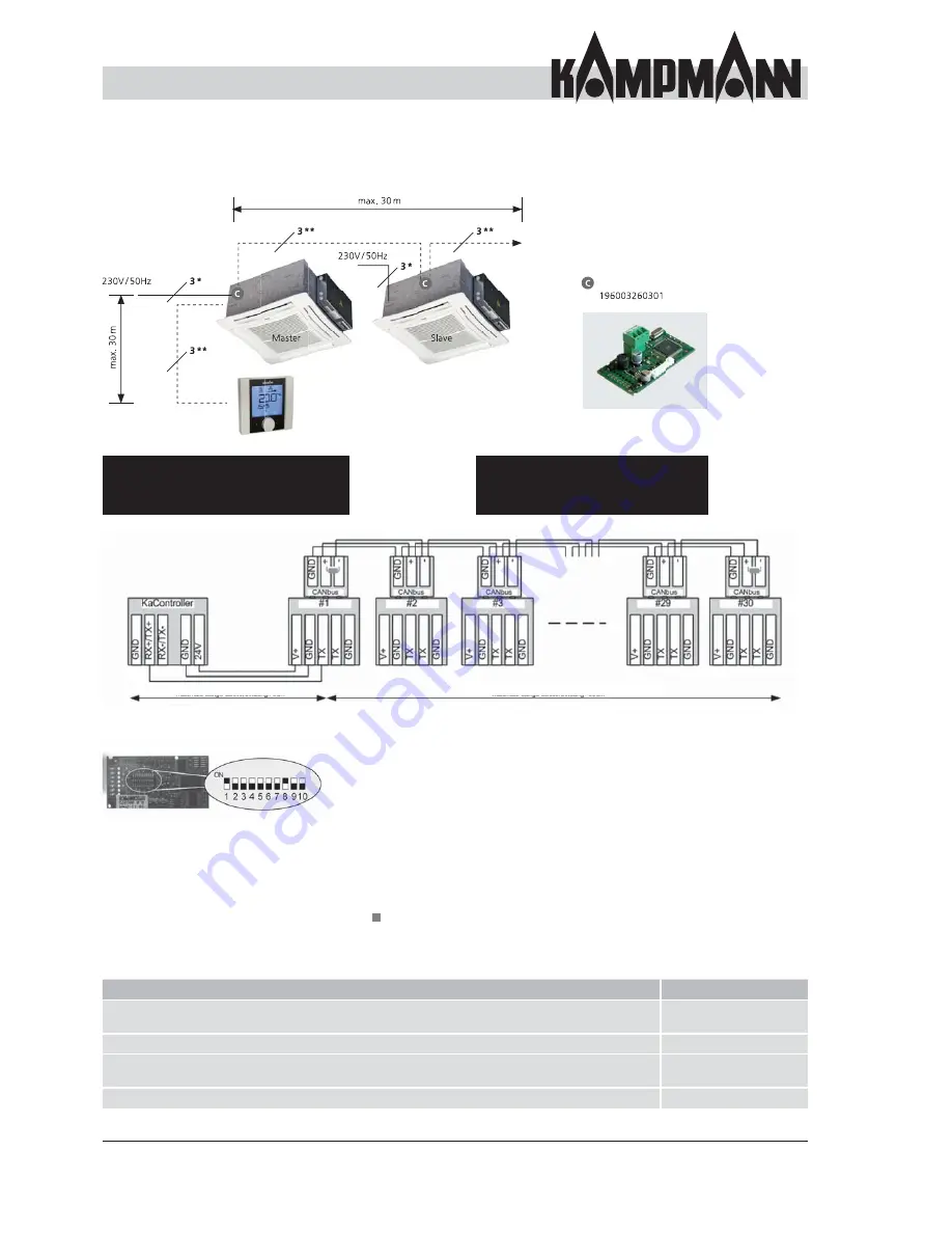
Wiring of group unit, KaControl, max. 30 units
Master and last slave unit need to be equipped with
a 120 Ohm on-site resistor.
If you wish, you can separately measure the
temperature for each unit via a room or air
intake sensor.
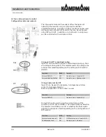
CAN bus card con
fi
guration using a DIP switch
setting (identical for all CAN bus cards):
1. Disconnect the KaCool.
2. Remove the CAN bus card from the basic PCB.
3. Set the DIP switch according to the illustration.
4. Plug the CAN bus card into the basic PCB.
5. Connect the BUS cable.
6. Switch on the power supply for the KaCool.
Set the DIP switches on all CANbus cards in a control circuit
identically!
DIP switches on the rear of the CAN bus card
DIP1 = ON
DIP2 = OFF
DIP3 = OFF
DIP4 = OFF
DIP5 = OFF
DIP6 = OFF
DIP7 = OFF
DIP8 = ON
DIP9 = OFF
DIP10 = OFF
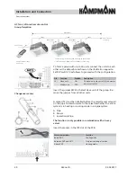
Maximum permissible cable lengths
Total length of BUS cables between the KaCool units
max. 500 m (CAT5)
max. 1000 m (Beldon 98)
Total length of BUS cable between the room control unit and master unit
max. 30 m
Total length between the KaCool and the external potential-free contacts, e.g. window contact,
external ON/OFF, etc.
max. 30 m
Total length between the KaCool and separate room temperature sensor
max. 30 m
Accessories: Operating unit with temperature
measurement: 196003210001 or 196003210002
Total per group,
max. 30 units
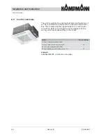
Accessories: CANbus card
Maximum length of bus connection: 500 m
Maximum length of bus connection: 30 m

