KaCool D HC
Assembly, installation and operating instructions
29
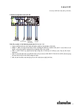
1
gr/ye
3
W1
N
PE
L
Mai
ns p
ower 230 V
A
C
1
2
gr/ye
Main
s power
su
pply
230 V/50
Hz
Fuse
(b
y othe
rs).
Re
fer
to
"El
ectrical
data” information
table
.
2
Juncti
on
bo
x
10
V
T/E
PE
N
L
KaCool
DHC
Elec
tr
ome
chanical
Unit
no
. 1
L‘
N
KP
Gnd
C
Uc
P2
AP
1
2
P1
3
4
5
VAL
Ri
=
100
K
Ω
Mai
ns p
ower 230 V
A
C
Thermostat
co
nne
ction
Motor connecti
on
Fau
lt me
ssage
s
Te
rminal box by
othe
rs
1
gr/ye
2
10
V
T/E
PE
N
L
KaCool
DHC
Elec
tr
ome
chanical
Unit
no
. 2
L‘
N
KP
Gn
d
C
Uc
P2
AP
1
2
P1
3
4
5
VAL
3
Ri
=
100
K
Ω
4
Mai
ns p
ower 230 V
A
C
Thermostat
co
nne
ction
Motor
c
onnecti
on
Fau
lt me
ssage
s
Juncti
on
bo
x
N
O
N
O
N
C
N
O
N
O
N
C
Building automation
syste
m (BAS)
1
2
AA1
0-10 V
AA1
GND
Fan spe
ed unit 1
Note
the i
nternal
resi
stance o
f the
u
nit!
COM
DI2
Filter
message
di
scharge un
it 1
Filte
r
message
di
scharge uni
t 1
(Contact
clo
sed
= faul
t)
3
4
DI1
DA1
Condensate
al
arm unit
1
(Contact o
pen = faul
t)
1
2
230V
2
gr/ye
1
gr/ye
1
2
2
1
2-pipe
heating/cool
ing
230V
DI3
5
DI4
DA2
Condensate
al
arm unit 2
(Contact o
pen = faul
t)
1
2
2-pipe
heating/cool
ing
230V
230V
1
2
AA2
0-10 V
AA2
GND
Fan speed
uni
t 2
Note
the i
nternal
resi
stance o
f the
uni
t!
COM
DI5
Filter
message
di
scharge un
it 2
Filte
r
message
di
scharge uni
t 2
(Contact
clo
sed
= faul
t)
3
4
DI6
5
3
W2
3
W3
5*
W4
3
W5
3
W6
5*
W7
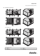
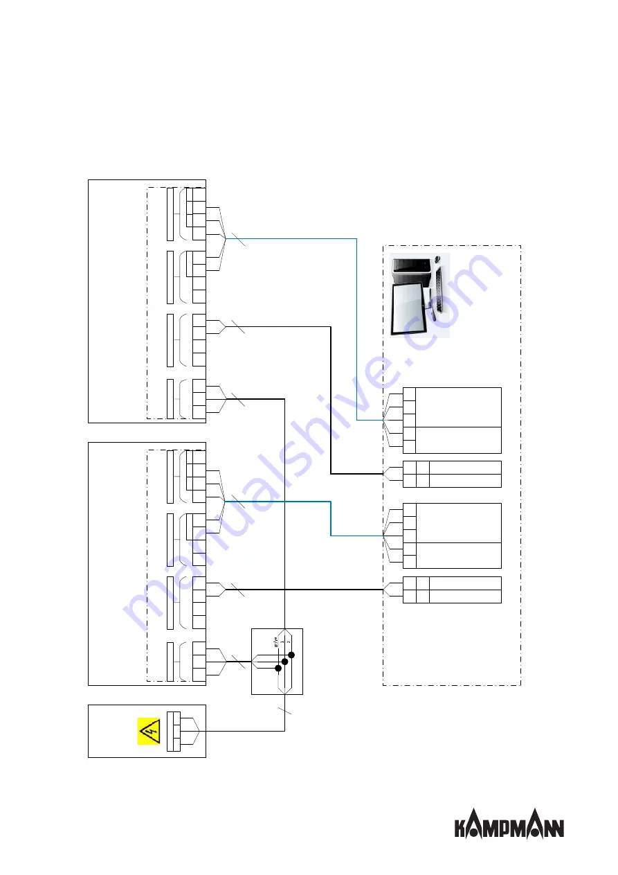
Cable laying with KaCool DHC (*00), control by DDC/BMS

