background image

KaCool D HC

Assembly, installation and operating instructions

7

2.2

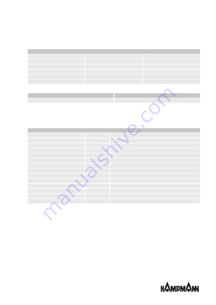
Limits of operation and use

Limits of operation

Min./max. water temperature

°C

4-90

Min./max. air intake temperature

°C

6--40

Min./max. air humidity

%

20-60

Min. operating pressure

bar/kPa

-

Max. operating pressure

bar/kPa

10/1000

Min./max. glycol percentage

%

0-50

Tab. 1: Limits of operation

Operating voltage

230 V/ 50/60 Hz

Power/Current consumption

On the type plate

Tab. 2: Operating voltage

We would refer to VDI-2035 Sheets 1 & 2, DIN EN 14336 and DIN EN 14868 with regard to the properties of the medium
used to protect the equipment. The following values provide further guidance.

The water used should be free of contamination, such as suspended substances and reactive substances.

Water quality

pH value (at 20 °C)

8-9

Conductivity (at 20 °C)

μS/cm

< 700

Oxygen content (O

2

)

mg/l

< 0.1

Hardness

°dH

4-8.5

Sulphur ions

not measurable

Sodium ions (Na

+

)

mg/l

< 100

Iron ions (Fe

2+

)

mg/l

< 0.1

Manganese ions (Mn

2+

)

mg/l

<0.05

Ammonia ions (NH

4+

)

mg/l

< 0.1

Chlorine ions (CI)

mg/l

< 100

CO

2

< 50

Sulfate ions (SO

4

2-

)

mg/l

< 50

Nitrite ions (NO

2+

)

mg/l

< 50

Nitrate ions (NO

3+

)

mg/l

< 50

Tab. 3: Water quality

Summary of Contents for KaCool D HC

Page 1: ...KaCool D HC Assembly installation and operating instructions Keep these instructions in a safe place for future use Issue06 21EN SAP No 1456278...

Page 2: ......

Page 3: ...data 12 5 Construction and function 13 5 1 Overview 13 5 2 Brief description 14 5 3 Wear parts list 14 6 Installation and wiring 15 6 1 Definition of the connection side 15 6 2 Requirements governing...

Page 4: ...inst reconnection 33 10 2 Maintenance Schedule 33 10 3 Maintenance work 34 10 3 1 Opening the inspection flap 34 10 3 2 Replacing the filter 34 10 3 3 Visual checks 35 10 3 4 Cleaning the condensate t...

Page 5: ...s apply as do general safety provisions governing the use of the equipment Illustrations in this guide are intended to provide a basic understanding and may differ from the actual model Ongoing tests...

Page 6: ...use described in Chapter 2 2 6 must be observed IMPORTANT NOTE Only use the unique after completion of the complete building and system Site heating is not deemed to be correct and proper use Intended...

Page 7: ...refer to VDI 2035 Sheets 1 2 DIN EN 14336 and DIN EN 14868 with regard to the properties of the medium used to protect the equipment The following values provide further guidance The water used shoul...

Page 8: ...perate the unit above electrical equipment such as switch cabinets computers or other electrical units or contacts that are not drip proof IMPORTANT NOTE Energy losses due to misuse Operating the unit...

Page 9: ...s i e Association of German Electricians VDE regulations DIN and EN standards DIN EN 1946 4 for compliance with advanced hygiene standards specifically for clean rooms hospitals medical practices etc...

Page 10: ...site IMPORTANT NOTE 2 people are needed to transport the unit Wear personal protective clothing when transporting the unit Only lift the unit on both sides and not by the pipes valves IMPORTANT NOTE M...

Page 11: ...ations and shocks IMPORTANT NOTE Under certain circumstances packages can carry storage instructions that exceed the requirements listed here Comply with these instructions accordingly 3 4 Packaging H...

Page 12: ...of basic unit mm 625 Panel width mm 580 Length of basic unit car cass mm 1250 Panel length mm 1180 Height of basic unit com plete mm 406 Weight of basic unit kg 56 5 Air volume flow m h 26 489 Interna...

Page 13: ...3 2 1 15 15 Fig 1 KaCool D HC at a glance 1 Air vents 2 Water connections 3 Actuator 4 Electrical junction box 5 Heat exchanger 6 EC radial fan 7 Filter cassette epm1 85 8 Condensate tray 9 Float swit...

Page 14: ...ugh an ePM1 55 filter and is passed through the copper aluminium heat exchanger Here the air is either heated or cooled depending on the temperature of the water in the heat exchanger Through the ePM1...

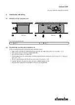
Page 15: ...the ceiling is sufficiently load bearing to take the weight of the unit Technical data 12 Make sure that the unit is securely suspended standing Ensure that the airflow can circulate freely Provide ad...

Page 16: ...air discharge can cause the air to fall and lead to uncomfortable downdraughts The minimum distance between the discharge sides and the wall must be 1 4 m If several units are installed they should ha...

Page 17: ...NOTE Horizontal installation of units When installing the units ensure that they are completely horizontal to ensure proper operation IMPORTANT NOTE Avoid draughts Consider the occupied zone when inst...

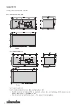
Page 18: ...ew Plan view Left side view Fig 6 Suspension points mm Note the Venkon minimum clearances when installing the basic units Mark the dimensions and distances of the key holes on the wall or ceiling as p...

Page 19: ...sels pressure relief valves and overflow valves Route condensation lines with a sufficient cross section without bends and narrow sections with a gradient to the in situ waste water pipe Allow adequat...

Page 20: ...ng heating me dium With cooling units there is a danger to the user from cold temperatures and a danger to the environment from the use of glycol Put in place appropriate safety measures Remove protec...

Page 21: ...C Assembly installation and operating instructions 21 6 5 2 Connection of 2 way valve kit 1 2 3 4 4 3 Fig 8 Dimensions in mm 1 2 3 4 4 3 Fig 9 Dimensions in inches 1 Return 2 Supply 3 Supply vent 4 Re...

Page 22: ...te from the basic unit providing no adequately sized condensate pump has been fitted in accordance with DIN EN 12056 formerly DIN 1986 100 However no condensate pump is factory fitted as standard Take...

Page 23: ...ent the condensate tray from overflowing Condensate drain Drainage of condensate from the condensate pump must be along a natural gradient with an adequate cross section minimum 1 2 Increase the cross...

Page 24: ...measured in the LNI laboratory pump operated with water not installed 20 dBA Noise level when installed at 1 m dBA measured in the Sauermann acoustic laboratory pump operated with water 27 dBA Power...

Page 25: ...closed Commissioning Open the cover Turn the selector dial and select the required switching point as per the Filter pressure loss table Close the cover again Filter type Starting pressure difference...

Page 26: ...Electromechanical control 7 2 1 Connection 00 Fig 12 PCB in the electrical junction box Power supply and control The unit needs a 230 V 50 Hz power supply The fan speed of the EC fan installed can be...

Page 27: ...D HC Comply with the details on cable types and cabling with due consideration of VDE 0100 Without NYM J The requisite number of wires including PE conductor is stated on the cable Cross sections are...

Page 28: ...ate controller Type 14894x 2 Junction box 10 V T E PE N L KaCool DHC Electromechanical Unit no 1 L N KP Gnd C Uc P2 2 1 W6 2 AP 1 2 P1 3 4 4 VAL 3 Ri 100 K gr ye 1 4 2 3 gr ye 1 2 Terminal box by othe...

Page 29: ...rmostat connection Motor connection Fault messages Junction box NO NO NC NO NO NC Building automation system BAS 1 2 AA1 0 10 V AA1 GND Fan speed unit 1 Note the internal resistance of the unit COM DI...

Page 30: ...ines have been properly connected Fill pipes and unit with water and bleed Check whether all bleed screws are closed Check leak tightness pressure test and visual inspection Check whether the parts ca...

Page 31: ...room sensor 3 control inputs functions parametrisable e g window contact presence detector heating cooling switchover Parallel operation of 2 units is possible Fig 14 Climate controller type 196000148...

Page 32: ...functions parametrisable e g window contact presence detector heating cooling switchover Parallel operation of 2 units is possible Fig 16 Climate controller type 196000148944 Climate controller black...

Page 33: ...or the proper and trouble free operation of the equipment If there are signs of increased wear during regular checks shorten the required maintenance intervals to the actual wear and teat Contact the...

Page 34: ...g 17 Opening the revision flap Carefully pull the revision flap down until it comes to a stop 1 and is held by the retaining cable Loosen the revision flap from the retaining cable 2 10 3 2 Replacing...

Page 35: ...nternal panels Dismantle the inspection cover and the air baffle as follows for visual inspections after the revision flap has been opened Fig 20 Unscrew the wing bolts on the inspection cover Fig 21...

Page 36: ...ements etc for soiling or deposits during maintenance and use a commercially available product to remove Then use commercially available disinfectant to disinfect the unit Clean the heat exchanger Che...

Page 37: ...ning panel with the float switch fitted Fig 27 Open the cover of the float switch Fig 28 Clean the float switch 10 3 6 Clean the inside of the unit Check all elements that come into contact with air i...

Page 38: ...done Check flow and return and tighten if necessary Water outlet Condensate drain outlets blocked Clean condensate outlets and check for ad equate gradient Chilled water line incorrectly insulated Che...

Page 39: ...ncing clips are removed during cleaning Fan dirty Clean dirt from fan Heat exchanger dirty Clean dirt from Heat exchanger 11 2 Start up after rectification of fault After correction of the fault carry...

Page 40: ...ticle Typ Model Nr artyku u Typ Model slo v robku auf das sich diese Erkl rung bezieht mit der den folgenden Norm en oder normativen Dokumenten bereinstimmt to which this declaration relates is in con...

Page 41: ...Zgodnie z postanowieniami Dyrektywy Odpov daj c ustanoven sm rnic 2014 30 EU EMV Richtlinie 2014 35 EU Niederspannungsrichtlinie Frank Bolkenius Lingen Ems den 11 06 2021 ____________________________...

Page 42: ...KaCool D HC Assembly installation and operating instructions 42...

Page 43: ...n and operating instructions 43 Table Tab 1 Limits of operation 7 Tab 2 Operating voltage 7 Tab 3 Water quality 7 Tab 4 Technical data condensate pump 24 Tab 5 Filter pressure losses 25 Tab 6 Maximum...

Page 44: ...rt Str 128 130 49811 Lingen Ems T 49 591 7108 660 F 49 591 7108 173 E export kampmann de W Kampmann eu Country Contact Great Britain Kampmann UK Ltd Dial House Govett Avenue Shepperton Middlesex TW17...

Reviews: