TIP
Assembly, installation and operating instructions
20
6.4.1 Connection to the pipe network
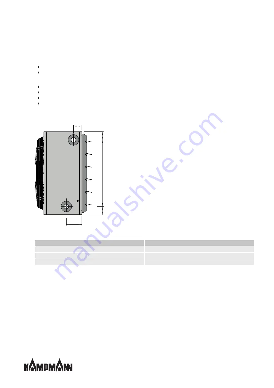
The flow and return connections protrude laterally from the housing. The heat exchanger connection dimensions are:
1" (series 54+55)
1 ¼" (series 56)
Proceed as follows when connecting up the unit's hydraulic pipework:
Disconnect the supply line from the medium.
Connect up the pipework.
Remove protective caps from the flow and return.
Seal the valve connections and screw in place.
Important! Use an appropriate tool (e.g. pipe wrench) to prevent connection spigots from being sheared off and
twisted. Ensure that the connections are installed tension-free!
70
130
70
70
A
Fig. 9: Connecting dimensions
Series
A [mm]
54
360
55
460
56
560
Summary of Contents for TIP
Page 2: ......
Page 40: ...TIP Assembly installation and operating instructions 40 12 Certificates...
Page 45: ......
Page 46: ......
Page 47: ......


