TIP
Assembly, installation and operating instructions
23
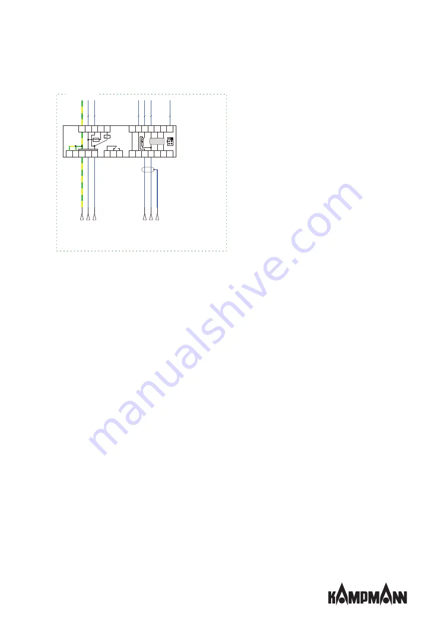
Terminal configuration for control of unit heater with EC fan
0.1AT
Ri > 49KΩ
B-
G
nd
Ub
A+
U
cM
U
cP
250V AC / 2A
PE L
N
C NC NO
D1 Ub Uc GND A+ B- SH
X1
B-
A+
GND
Uc
Ub
D1
S
Ls
N
L
PE
PE PE
AD
EC
mSM_
L
SH
PE
L
N
0
-1
0
V
G
n
d
*)
rt
ge
bl
br
bl
gn
ge
w
s
Mains 230 V/50 Hz
Potential-free
fault alarm not
available
Control signal 0-10 V DC
*) Control line max. 100 m. Lay
shield from 20 m only on signal
source side (PE).
Fan connection side
Summary of Contents for TIP
Page 2: ......
Page 40: ...TIP Assembly installation and operating instructions 40 12 Certificates...
Page 45: ......
Page 46: ......
Page 47: ......


