TIP
Assembly, installation and operating instructions
28
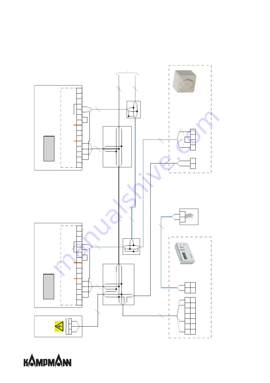
7.2.5 Cabling of TIP(**00), actuation by speed controller type 30510 with clock thermostat type 30056
N
PE
L
1
2
gn/
ge
3
W
1
gn/
ge
1
2
2
1
PE
PE
PE
L
N
C
N
C
N
O
D
1
U
c
U
b
GN
D
A
+
B
-
SH
R
i >
4
9
KΩ
gn/
ge
1
2
2
1
PE
PE
PE
L
N
C
N
C
N
O
D
1
U
c
U
b
GN
D
A
+
B
-
SH
R
i >
4
9
KΩ
2*
W7
3
W2
2*
W3
3
W6
3
W12
2*
W13
1
2
1
2
L
N
C
S
C
S
+
-
1
2
1
2
2*
*
W1
1
gn/
ge
1
2
g
n/
ge
1
2
1
2
3
gn/
ge
1
2
4
1
2
gn/
ge
1
2
g
n/
ge
1
2
1
2
g
n/
ge
3
W8
2*
W9
1
2
3
4
1
2
4
5
6
7
L
K
8
9
3
H
L
N
5
W10
F
F
1
2
3
W
4
2*
W
5
Speed controller, type 30510
Clock thermostat, type 30056
Mains
230 V
In situ fusing.
Observe
"Electrical data"
information table.
Mains 230 V
Unit no. 1
Jumper ex-
works
TIP EC, electromechanical
TIP EC, electromechanical
Unit no. 2
1) To further units
(refer to Information
for maximum number)
In situ terminal box
Junction box
Junction box
Jumper ex-
works
In situ terminal box
1)
Room sensor, type FL 103
Heating
See clock thermostat instruction for
further information
Summary of Contents for TIP
Page 2: ......
Page 40: ...TIP Assembly installation and operating instructions 40 12 Certificates...
Page 45: ......
Page 46: ......
Page 47: ......


