18
1.54
Ultra
Comfortable indoor climate in high-end interiors
Installation and operating instructions
9.3 Electrical connections
• The condensation pump is fixed to the top of the unit with a rubber pad
and can be simply removed for installation and cabling work.
• Connect the voltage supply and alarm contact (separate cable with plug)
as per the wiring diagram on page 17 (only with Ultra without KaControl
module, recirculation air).
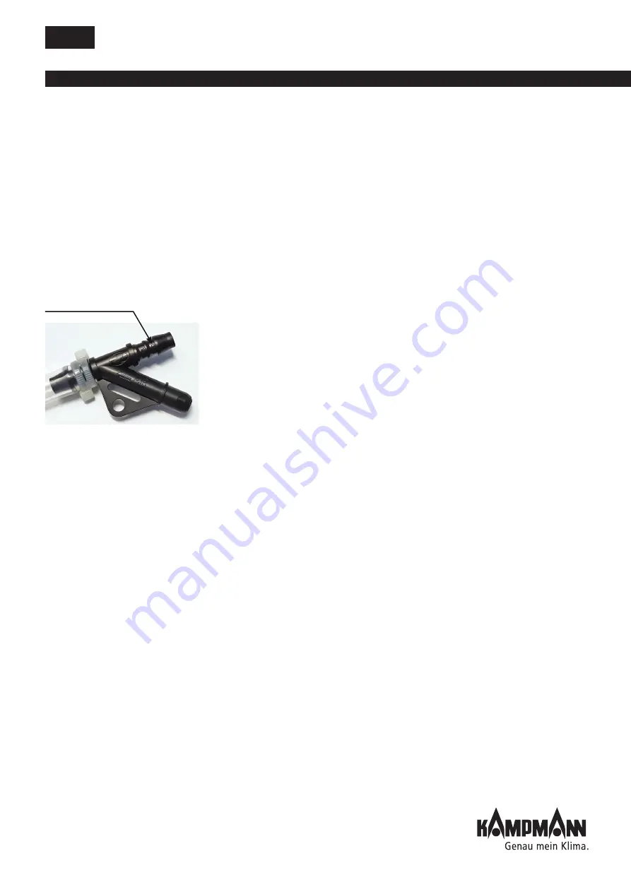
• Then connect the 6 mm-diameter hose (provided on site) to the
condensation drain on the vent valve (see diagram on left) and secure in
place with cable ties.
9.4 Commissioning and functional testing of the condensation
pump
• Switch on the mains voltage.
• Pour water into the condensation tray. The pump should switch on
automatically and switch itself off again.
• Test the alarm switch: add water until the alarm switch is triggered
(acoustic or visual warning message fan switches off or similar).
9.5 Warning information/Technical data on condensation
pump
• Check the float switch with the coarse screen regularly and clean if
necessary.
• Regularly check the condensation drain.
• Refer to the technical literature on the condensation pump.
• Refer to chapter 1.3, pages 7-8, for technical data and limits of use.
Caution!
In the initial phase of cooling, it is possible that a white film forms in the
condensation tray, mainly on the outer edge. This is simply residue from the
protective layer in the heat exchanger and can simply be wiped away with
a cloth.
Connect a hose here and secure with
cable ties!
Vent valve


