24
1.54
Ultra
Comfortable indoor climate in high-end interiors
Installation and operating instructions
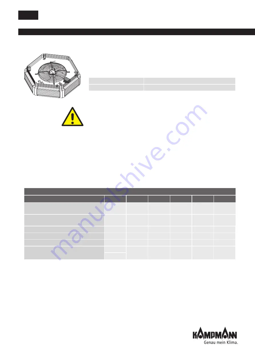
10.3.1 Three-phase motor
The three-phase external rotor motor can be switched between two stages
using a 2-stage three-phase switch (Y/Δ configuration). The motor in each
of the two switching configurations (Y or Δ) can be switched between 5
stages by voltage reduction using a 5-stage three-phase controller.
The fans are operated with a clockwise rotating field!
Important:
Operation of this unit on frequency converters is only permitted
if the frequency converter has a sinus filter effective on all poles. Missing
sinus filters can lead to severe thermal damage to the fan motor. In this case,
the manufacturer accepts no warranty.
Three-phase parallel connection
• Several Ultra units, even of different sizes, can be connected in parallel to
a stage switch if the switching power of the stage switch is not exceeded.
• The thermal contacts of all Ultra unit heaters have to be switched in
series.
• If several Ultra unit heaters are connected to a single-phase controller, we
recommend the use of intermediate terminal boxes.
Ultra with motor junction box
Switching stage 1
Y-connection
Switching stage 2
Delta connection
Max. number of connectible Ultra unit heaters
Description
Type
I
max.
73 _ _ 36
84 _ _ 36
85_ _ 36
96 _ _ 36
2-stage three-phase switch with room thermostat
connection
30049
10 A
30
30
28
10
2-stage three-phase switch with room thermostat
connection
30051
10 A
30
30
28
10
5-stage three-phase controller 2 A
30751
2 A
20
10
7
2
5-stage three-phase controller 4 A
30752
4 A
30
20
14
5
5-stage three-phase controller 8 A
30754
8 A
30
30
28
10
Electronic 2-stage three-phase controller
30177
10 A
30
30
28
10
30277
298593
647752
650097


