28
1.54
Ultra
Comfortable indoor climate in high-end interiors
Installation and operating instructions
Control signal Ultra speed
0-1.0 V
OFF
1.0-9.5 V
0-100 %
9.5-10.0 V
100 %
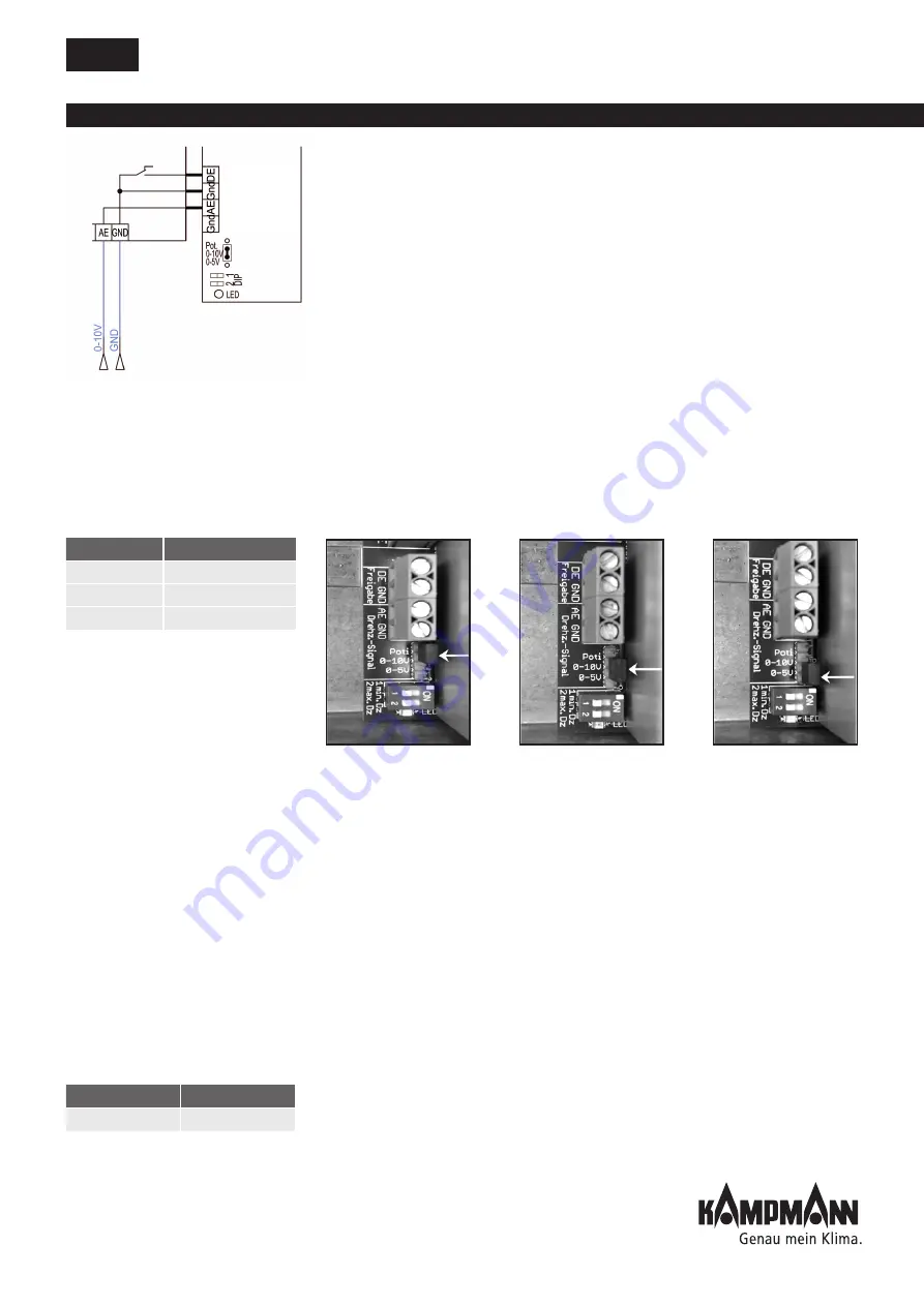
Connection example 0-10 V
Table 2
Control via 0-100a 0-100 KΩ potentiometer
When controlling using a 0-100 KΩ potentiometer (linear), the jumper
on the master unit (the Ultra connected to the potentiometer) must be
connected to the potentiometer (see Fig. 3). All other Ultras (slave units)
should then have jumper position 0 - 5 V (see Fig. 3).
Control via 0-10 V DC
When controlling with 0-10 V DC, the jumper must be connected to 0-10 V
on all power units (refer to Fig. 2). The 0 - 10 V control signal is interpreted
with respect to its speed according to the table (refer to table 2). Input
resistance Ri > 100 kOhm.
Control via 0-5 V DC
When controlling with 0-5 V DC (for instance control by others), the
jumper must be connected to 0-5 V on all power units. The speed does not
behave linear to the control voltage with this setting (refer to Fig. 3). Input
resistance Ri > 100 kOhm.
Fault signal output
In addition to the motor fault signal alluded to in the paragraph
”Continuously variable power module type ...V“ in Chap. 10.2.1, the
overheating of the power module is signalled via the potential-free N/C
(60 V AC/DC max. 1 A). In the event of a fault, the control signal has to be
locked to 0 V via the controller.
Voltage supply and fuse
The fan and power module are together supplied by one line with
230 V/50 Hz voltage. An operating indicator LED is positioned on the
connecting PCB in the power module.
A unit fuse Ø5x20 mm is also installed as a main fuse on the connecting PCB
and a TR5 fuse on the power PCB. Refer to Table 3 for values. Maximum
on-site fuse 10 A.
Fig. 1:
Jumper to
potentiometer
Fig. 2:
Jumper to 0 - 10 V
Fig. 3:
Jumper to 0 - 5 V
Connecting PCB
Power PCB
T2.5 A
F2.5 A
Table 3
Activation
Speed signal
Control signal
for fan speed
0..10 V D


