30
1.54
Ultra
Comfortable indoor climate in high-end interiors
Installation and operating instructions
The fan and the KaControl recirculation air module can be disconnected
from the mains power supply via the integral master switch.
All additional electrical components are not disconnected from the mains
power supply by the master switch!
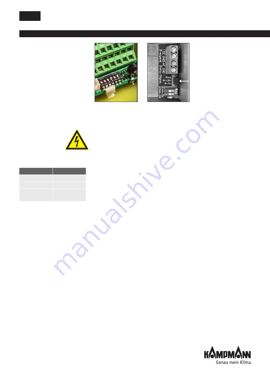
0-10 V DC control signal
The 0-10 V DC control signal at input terminals AI2 and GND (Ri = 20 kOhm)
on the KathermBoard is interpreted as per Table 6 with regard to speed
and valve control. To guarantee a reliable start up, the fan is operated
for 30 seconds at 120 V AC. A minimum voltage limit of 100 V AC is
factory-set.
The maximum limit can be set, as described in Chapter 10.3.2.2. via DIP
switches on the power module or alternatively via the KaControl system.
Maximum permissible cable length for the 0-10 V DC control signal is 20 m.
Use a shielded cable e.g. J-Y(St)Y, 0.8 mm.
Output terminals V1 and GND are available on the KathermBoard to control
a 24 V DC Open/Close actuator. Maximum permissible load 0.5 A
A wet fault message 24 V DC/ max. 0.5 A is available at terminals V2 and
GND after appropriate parametrisation with an additional KaController unit.
KaControl system
Please refer to the KaControl installation instructions for unit heater I438 for
information on the KaControl system.
DIP switch KathermBoard
Jumper on power module
Control signal
Function
0 – 3 V
Unit OFF
3 – 9 V
Valve Open
4 – 9 V
Min. fan speed
... 100%
Table 6


