


34
1.54
Ultra
Comfortable indoor climate in high-end interiors
Installation and operating instructions
There is no fault signal contact in the fans in models 84 and 85. In the event
of a fan fault or power failure at the unit heater, this is not reported via the
KaControl system!
Switch the unit on and off via the control input.
Do not switch the unit on and off via the mains power supply.
KaControl system
Please refer to the KaControl installation instructions for unit heater I438 for
information on the KaControl system.
Voltage supply and fuse
The fan and KaControl module are together supplied by a supply line with
230 V/50 Hz voltage. An operating indicator LED is positioned on the
connecting PCB in the KaControl module. A unit fuse Ø 5x20 mm is also
installed on the primary side for the control voltage and possibly for the
power supply to the condensation pump as well as on the secondary side
for 24 V voltage and a unit fuse Ø 5x20 mm on the Katherm Board. Refer
to Table 10 for values. Maximum on-site fuse 16 A.
11. Commissioning
11.1 Pre-commissioning checks
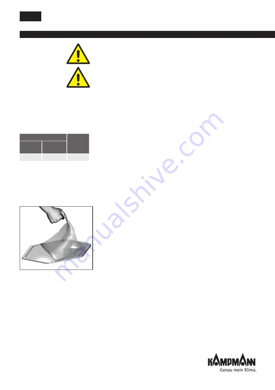
The base of the Ultra is covered with a transparent film to protect it from
damage during transport and installation.
• Remove the film once the Ultra has been commissioned, by loosening a
corner and then pulling it off.
Perform the following checks before commissioning the Ultra.
• Is the Ultra properly and securely fixed in place?
• Is the protective conductor connected properly on all units?
• Are the AC fan thermal contacts wired correctly (where several Ultras
are connected in series (does not apply to continuously variable power
module))?
• Are the EC fan fault signalling contacts wired correctly, if fitted (where
several Ultra unit heaters are connected in series)?
• Are all the lines connected properly as per the wiring diagrams?
• Are the jumpers and DIP switches correctly set?
• Note the information on commissioning of other system parts and the
KaControl system.
Connecting PCB
KathermBoard
Control
voltage
24 V
voltage
T 1.0 A
T 315 mA
T 5.0 A
Table 10
Removing the film*
* With non-standard colours, the base
cover can be covered with a foam film
glued on.


