Aetos Installation Manual
9.2
Port 1 – Auxiliary RS-232
1
5
6
9
Figure 28:
Service port D-SUB male with designated pins.
Pin
Description
1
External push button input.
2
Terminal RX (RS-232)
3
Terminal TX (RS-232)
4
12 V output, max 200 mA
5
GND – ground
6
Port 1 auxiliary RX (RS-232)
7
Port 1 auxiliary TX (RS-232)
8
Alarm switch – reserved for future use.
9
GND – ground
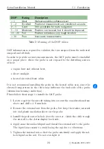
Table 5:
Description of the service port pins.
parity bit, one stop bit. Figure 29 illustrates the connection.
A communication with a terminal shall be used only during production and
factory maintenance or repair.
1
5
6
9
GND
Ter TX
Ter RX
Terminal device TX
Terminal device RX
Terminal device GND
Figure 29:
Connection schematics for service terminal.
9.2
Port 1 – Auxiliary RS-232
Aetos has three RS-232 communication ports used to connect to third party
devices, see page 39. We recommend to use them first. However, if needed,
an additional RS-232 communication can be established trough the service
36
©
Kanardia
2019–2020


