Aetos Installation Manual
10.3
Connection Details
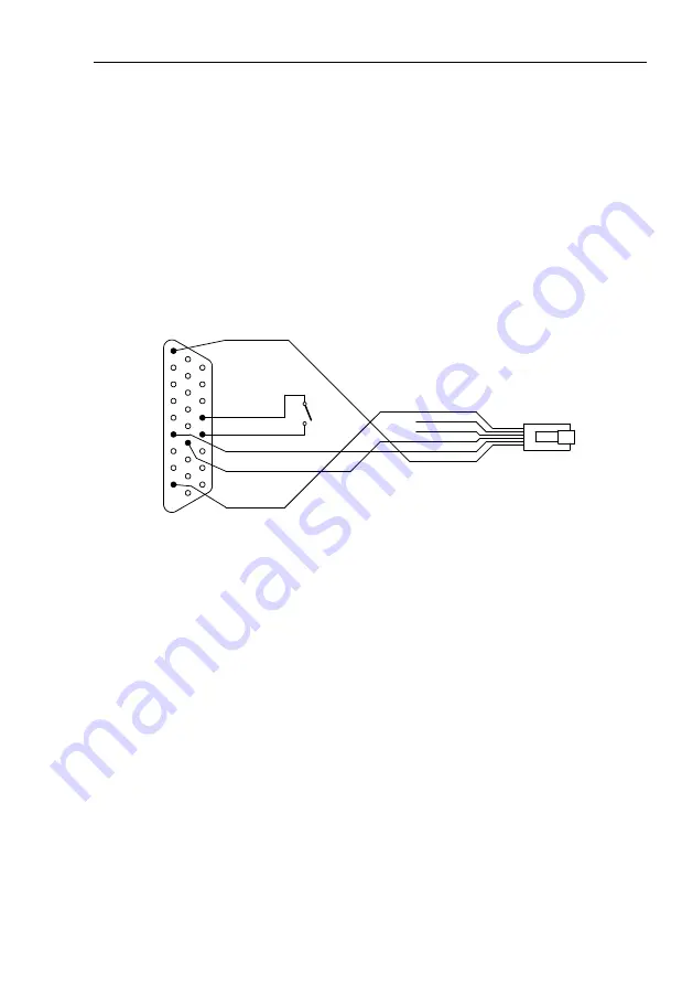
It is also assumed that Aetos will provide power for AT1.
In order to turn AT1 on, a switch between pins 22 and 23 is required. When
switch is closed, AT1 is turned on and vice versa. Alternatively, pins 22 and
23 can be permanently connected. In this case, AT1 is powered on as soon
Aetos is powered on.
A separate power line can be provided for AT1. In this case, do not connect
pin 1 on AT1 with pin 1 on RJ12. However, pin 6 on RJ12 and one of GND
pins on AT1 shall be connected.
26
19
10
18
9
1
AIR Traffic AT1 - 26 pin D-SUB26 HD
1 ... +12 V
2
3
4 ... RX
5 ... TX
6 ... GND
1 ... V in (+12)
13 ... TXD3
4 ... RXD3
22 ... Enable EN
23 ... GND
9 ... GND
RJ12 - 6 pin
Not used
Figure 47:
Schematic connection for AIR Traffic AT1 device.
Configuration
The AT1 devices can’t be configured with Aetos and one of the procedures
from device’s manual shall be used. The WiFi solution is shown next.
Turn the AT1 on. AT1 will act as an WiFi access point. Connect a computer,
a telephone or a tablet to the
AIR-Traffic
SSID and establish connection
per device’s manual. Once connection is established, open the browser with
correct URL address. Figure 48 shows the situation after the connection was
made and device data was synchronised.
Set the HEX code –
Own ICAO Address
of your transponder.
Aetos will connect to data port 3. Default protocol for port 3 is Garmin TIS
protocol. This must be changed. At the same time we also recommend using
higher baud rate. In order to change this, select the
Advance Configuration
button and scroll down until the RS-232 data port section. Figure 49 shows
settings we used.
51
©
Kanardia
2019–2020


