


Variometer — Manual
2. Installation
droid device to your Indu Variometer. Please read our Customizer
Manual for more information.
2
Installation
The Indu variometer requires a standard size 80/57 mm hole in the
instrument panel. The position of the hole must ensure visibility
from the pilot’s perspective.
2.1
Mounting Dimensions
The mounting screw holes are located on a circle of 89/65 mm diam-
eter. The instrument is mounted using four screws type M4. To pre-
vent internal stresses, please make sure that the instrument panel is
flat. It is highly recommended that the instrument panel is mounted
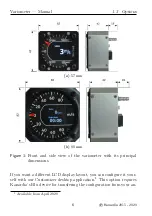
using rubber shocks, which reduce the vibrations. Figure 2 illustrates
the panel cutout and mounting holes.
2.2
Connections
Figure 3 illustrates all connections at the back side of the instrument.
2.2.1
Static Pressure -
Pst
Indu Variometer must be connected to the static pressure source.
Static pressure source is usually obtained from pressure sources lo-
cated on the fuselage side surfaces or from the static port on the pitot
tube.
Locate the existing tube, cut it at an appropriate place and insert a
T junction. Install a new tube from junction to the instrument.
7
©
Kanardia
2015 - 2020