Nesis III — Installation Manual
2.4
Mounting Procedure
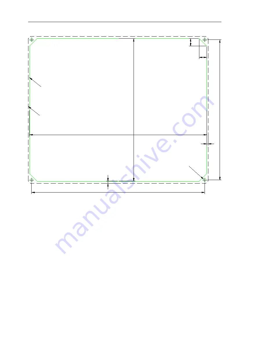
Dashed line
represents bezel outer contoure.
Green line is coutout line.
A tolerance of 0.4 mm was already added.
No extra tolerance is needed.
Drill 3.5 mm hole
to fit M3 screw.
211,1
1
6
9
,7
9
9
206,3
1
6
6
,9
2
,6
1,6
Figure 4:
Nesis cutout dimensions. The figure is not actual size!
2.4
Mounting Procedure
Once the appropriate opening is made in the instrument panel, test mount
the display. Adjust the opening if necessary.
There are several ways to fix the Nesis into the panel:
using supplied M3 nut and lock washer,
using self-clinching nut insert,
using threaded rivet nut insert,
using spacer stud and epoxy.
Details are shown in next subsection.
14
©
Kanardia
2018


