Copyright
©
Kanda 2013
9
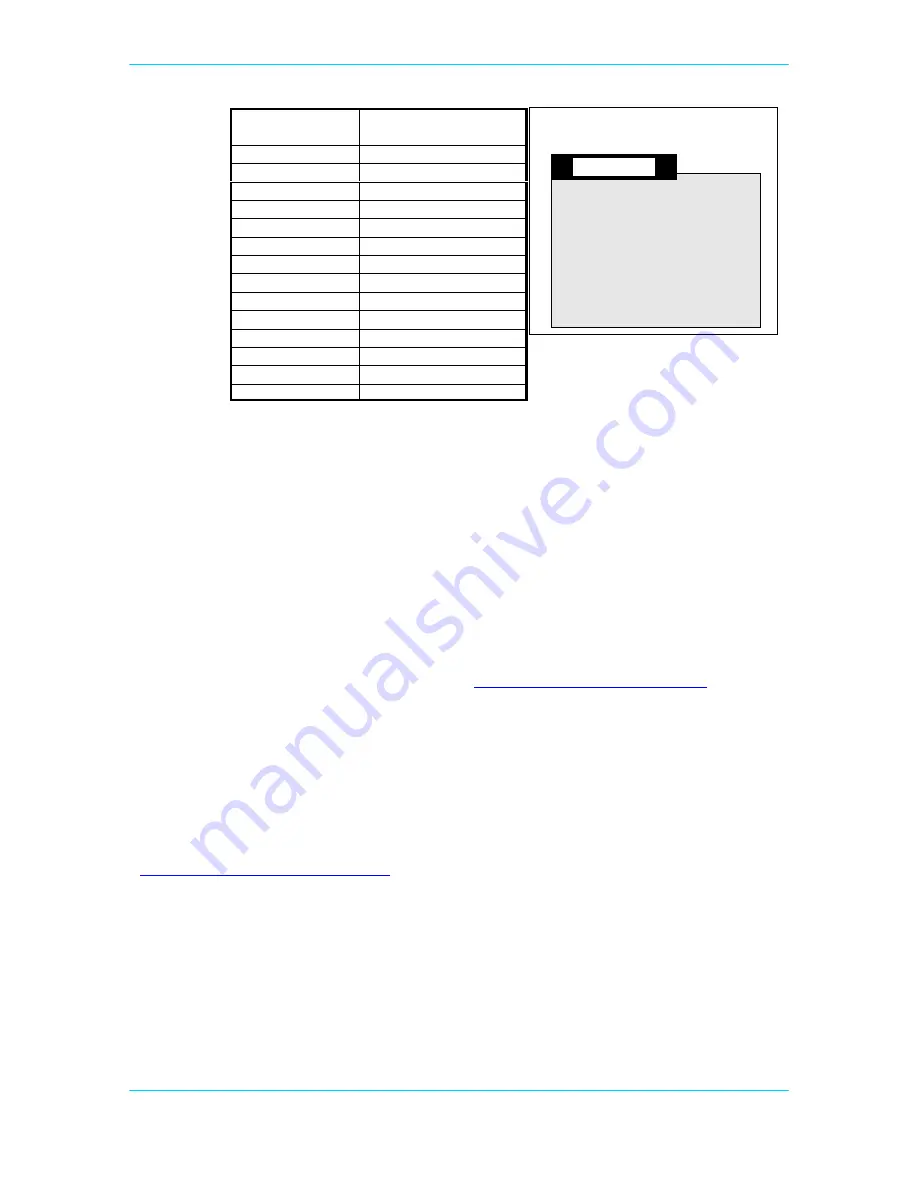
Connection
Name
Function
0V
Ground 0V
+5
Vcc - must be 5V
Vo
Contrast
RS
Register Select- A14
Wr
Not Write
E
Enable
D0
Data Bit 0
D1
Data Bit 1
D2
Data Bit 2
D3
Data Bit 3
D4
Data Bit 4
D5
Data Bit 5
D6
Data Bit 6
D7
Data Bit 7
The board is designed for use with an LCD with a Hitachi driver chip built-in, with a
contrast pin voltage of 0 to 5 Volts. If no characters appear on LCD, then you may need
to change resistors R22 and R23 to alter the contrast voltage, especially if you use a
different LCD.
This board is not designed for use with back lit LCD modules, so the extra connections
needed are not included and the power supply will not supply the current required.
The LCD can be driven in Memory Mapped or I/O Mode - see data sheet. If the crystal
has been changed to a faster crystal frequency, memory mapped operations will not
work.
A suitable LCD is available on the Kanda site (
http://www.kanda.com/go/570910-PM
)
A sample file is included on the CD in Samples directory.
External Memory
The board is fitted with sockets for an address latch (74HC573) and a Flash RAM chip
(29C256).
These are available as a pair from Kanda –
http://www.kanda.com/go/STK200-RAM
STK200 or STK300
Board
LCD
LCD Connector 14 x 1
LCD mounted outside the board


