


INSTALLATION INSTRUCTIONS
We recommend installation by a specialist workshop.
If you have any technical questions, please contact us at
support@kuk-martendefence.com
SAFETY INFORMATION
• WARNING: HIGH-VOLTAGE!
High voltage is not harmful to healthy persons. You should, however, avoid contact with the contact plates. This applies in particular to people with heart disease
or heart pacemakers.
• WARNING: OVERVOLTAGE PROTECTION!
Remove the fuse when jump starting, carrying out welding work and for rapid charge. There are particular safety regulations applicable when
working on electric and hybrid vehicles. Please observe the logbook for the vehicle with regards to this.
• We can only guarantee the full functioning of the device for vehicles with a 12V battery.
• Connection to a 24V battery is possible if you use a voltage transformer.
• Always protect the marten repellent device against excessive heat and prevent or eliminate dirt on the contact plates.
• Always comply with the working steps in these installation instructions and the safety information.
• Damage caused by not observing the installation instructions is excluded from any liability.
• Clean the engine compartment and parking space thoroughly before installation in order to avoid turf wars
(we recommend the K&K scent mark remover for the engine compartment, item 000300) (8).
Intended use:
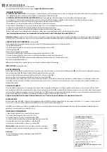
The device is used to expel martens and other wild animals from the vehicle engine compartment by means of electric shock and aggressive, pulsating ultrasound frequencies.
After the marten has triggered a short circuit, the high-voltage function is switched o for a short time in order to give the animal the opportunity to escape.
FUNCTION TEST
prior to installation
All devices are carefully checked by us multiple times. Please also carry out the following nal checks:
1) Remove
(A)
the fuse
(1)
2) Connect the device to the positive and negative pole/earth of the car battery/vehicle body
(E)
3) Insert fuse
(F)
4) Don’t touch the contact plate
(3)
any more
5) LED
(5)
ashes to indicate it is working. This can take a few minutes.
(H)
6) High voltage can also be measured using a digital multimeter on the contact plate
7) Remove the fuse
(A)
(WARNING! After removal, contact plate will carry approx. 3 minutes of residual current)
8) End of function test
Info:
Warranty is exclusively for the device. There is no assumption of assembly and disassembly costs!
INSTALLATION
when fuse has been removed
CONTROL UNIT
Mount the basic device
(2)
in a place where it cannot overheat (e.g. not directly on the exhaust manifold)
(B)
and the ultrasound can radiate as freely as possible in order to avoid
acoustic shadow
(D)
. The fuse holder
(1)
should be mounted so it is easily accessible.
Connection of the positive cable with fuse holder to the positive pole of the 12V battery or comparable positive terminal
(E)
.
Connection of earth cable to minus pole of the 12V battery or vehicle earth
(E)
.
Connection of the vehicle terminal 15 cable
(6)
to wiring system’s vehicle terminal 15 or another contact, which is switched to negative for parked vehicles and positive for running engines
(E)
.
If the cable is connected, the system switches o when the engine is running and switches back on again once the engine is turned o. If the cable is not connected, the system is in continuous
operation.
CONTACT PLATES
Lay the contact plates strategically in bite-endangered areas in the engine compartment and secure them with cable ties. The high-voltage cable should not be placed anywhere near hot and/or
rotating engine parts
(B)
. Contact plates should be mounted at a minimum distance of 10mm to other conductive parts and in such a way as to ensure they are protected from water (short-circuit
hazard)
(C)
. The contact plates should be installed so that the martens can simultaneously touch another conductive part to trigger an electric shock. An earthing mat can be added as support
(item 1003).
Please attach the yellow warning sticker ‘Warning high voltage’ (7) so it can be clearly seen in the engine compartment (G)!
INITIAL OPERATION
Re-insert the fuse
(F)
. If the device has been correctly connected, the control LED
(5)
on the basic device will start to ash (approx. every 3-12 seconds). This procedure may take a few minutes
when operating for the rst time
(H)
. In this state, do not touch the contact plates.
The M3500N is an eective and comprehensive defence solution. It combines ultrasound and high voltage in order to achieve the best possible defensive performance. Despite this, we cannot
guarantee that the martens will be expelled in 100% of all cases.
MORE INFORMATION
If the device does not work, it could be for the following reasons:
1) Operating voltage is not between 1,5V and 15V.
2) The cable to vehicle terminal 15 has not been connected correctly
(E)
.
3) The contact plates are touching other conductive parts (short circuit)
(C)
.
4) Fuse is not in the fuse holder or is faulty
(1)
.
5) There is a delay of several seconds when switching on. Have patience
(H)
!
Disposal:
The device may not be disposed of in household waste.
Please contact your local authority for the correct disposal method.
Accessories
- Bonnet switch for immediate discharge No 1001
- Earthing mat No 1003
TECHNICAL DATA
• Operating voltage: 12 V car battery
• Average power consumption: < 5 mA
• Battery monitor: switches o automatically
when battery voltage < 11,5V (±5%)
• Ultrasound frequency: approx. 22 kHZ (± 10%)
• Sound pressure: approx. 100 dB (± 15%)
• Radiation angle: approx. 150°
• Loudspeaker: ceramic special Piezo loudspeaker
with aluminium dome-shaped diaphragm
• Output voltage: approx. 200 - 300 V
• Operating temperature range: approx. -25C to +80°C
• Function display: lashing LED (approx. every 5 - 12 sec.)
• Dimensions of control device: approx. 120 x 80 x 40 mm
• High-voltage contact plates: 6 x, each approx. 40 x 40 x 1.5 mm
• Cable length of high voltage cable: approx. 4 m (± 10%)
• Fuse in fuse holder: 500 mA
Approved by the Kraftfahrt-Bundesamt (Federal Motor
Transport Authority) with the E1 symbol.
EN


