background image

7. Interfaces and Communication


  - 231 - 


CRC Check


In Modbus-RTU mode, a message includes a CRC-based error-check field. The CRC field 
checks content of entire message. The CRC field is two bytes, containing a 16-bit binary 
value.  The  CRC  field  is  calculated  by  transmitting  device,  and  then  added  to  message. 
The  receiving  device  recalculates  a  CRC  value  after  receiving  message,  and  compares 
the calculated value with the CRC value in the received CRC field.


The CRC is first stored to 0xFFFF. Then a procedure is invoked to process the successive 
8-bit  byte  in  the  message  and  the  value  in  the  register.  Only  the  eight  bits  in  each 
character are used for the CRC. The start bit, stop bit and the parity bit do not apply to the 
CRC.


During generation of the CRC, each eight-bit character is in exclusive-OR (XOR) with the 
content in the register. Then the result is shifted in the direction of the least significant bit 
(LSB), with a zero filled into the most significant bit (MSB) position. The LSB is extracted 
and examined. If the  LSB  was a 1, the register then  performs XOR with  a  preset value.    
If the LSB was a 0, no XOR is performed. This process is repeated until eight shifts have 
been  performed.  After  the  last  (eighth)  shift,  the  next  eight-bit  byte  is  in  XOR  with  the 
register's current value, and the process repeats for eight more shifts as described above. 
The final value of the register, after all the bytes of the message have been applied, is the 
CRC value.


The CRC is added to the message from the low-order byte followed by the high-order 
byte. The CRC simple function is as follows:


unsigned int crc_chk_value

unsigned char *data_value,unsigned char length


{


unsigned int crc_value=0xFFFF; 

int i;


while

length--


{


crc_value^=*dat+; 

for

i=0;i<8;i++


{


if

crc_value&0x0001


{


crc_value=

crc_value>>1

^0xa001;


}


else


{


crc_value=crc_value>>1;


}


}


}


return

crc_value

;


}


7


Summary of Contents for GT600-4T132G

Page 1: ...GT600 AC Drive...

Page 2: ...for professional incorporation into a complete machine or process system It is the responsibility of the user or machine builder or installation contractor or electrical designer engineer to take all...

Page 3: ...Installation 44 3 1 Typical System Connection 44 3 2 Main Circuit Wiring 45 3 3 Control Circuit Wiring 61 3 4 Wiring Checklist 70 Chapter 4 Operating Panel Keypad Display 72 4 1 Introduction 72 4 2 I...

Page 4: ...cket 274 Chapter 9 Maintenance and Inspection 280 9 1 Daily Inspection 280 9 2 Periodic Inspection 282 9 3 Lifetime of Fans and Electrolytic DC Bus Capacitors 284 9 4 Storage 288 9 5 Warranty Agreemen...

Page 5: ......

Page 6: ...stored electrical energy in the DC bus capacitors even after power OFF These high voltages are potentially lethal The AC Drive is NOT intended to be used for safety related applications functions The...

Page 7: ...the AC supply has been disconnected The AC supply must be isolated at least 10 minutes before any work can be undertaken as the stored charge will have been discharged through the internal bleed resi...

Page 8: ...Please consult with the motor manufacturer who can provide cooling solutions such as a electric force ventilated fan or an AC Drive rated AC motor designed to handle reduced speed running with AC Dri...

Page 9: ...5 1 Product Information 1 1 Product Type Identification 8 1 2 Internal View of GT600 9 1 3 Ratings 13 1 4 Technical Specifications 14 1 5 De rating 18...

Page 10: ...112 0A 0 500Hz 55kW Serial No Serial No 010140374FB00005 Version Chapter 1 Product Information 1 1 Product Type Identification Each model in the range of the drive systems has a model number that iden...

Page 11: ...iably Ground bar Ground the PG card and control board only after ensuring reliable system grounding Control circuit terminals See section 3 3 1 Fixing pin of extension card See sections 8 4 1 and 8 4...

Page 12: ...3 Cabling tray and fixing pin of ground cable of control board This ground cable can only be connected to the ground bar after the system is grounded reliably Otherwise connect it to the fixture Grou...

Page 13: ...tion8 3 Controlcircuit terminals See sections3 3 Logo Cable clamp Housing Live indicator Do not remove install the drive when this indicator is lighting EMC and VDR screw Refer to Power Grid System in...

Page 14: ...Refer to Power Grid System in section 3 2 2 and requirement on current leakage in section 9 1 8 Input terminals R S T See sections 3 2 Bottom hoist hole Output terminals U V W Operating panel See sec...

Page 15: ...18 5 22 30 37 45 55 75 90 110 132 160 HP 25 30 40 50 60 75 100 120 150 180 220 Output current A 37 45 60 75 91 112 150 176 210 253 304 Default carrier frequency kHz 6 6 6 5 5 4 3 3 3 3 3 Overload cap...

Page 16: ...82 Rated input frequency 50 60 Hz 5 Power capacity kVA 334 375 404 453 517 565 629 716 Drive Output Applicable motor kW 200 220 250 280 315 355 400 450 HP 267 293 333 373 420 473 533 600 Output curren...

Page 17: ...aking 0 to 100 Jog running Frequency range of jog running 0 00 to 50 00 Hz Acceleration Deceleration time of jog running 0 0s to 6500 0s Onboard multiple preset speeds The system implements up to 16 s...

Page 18: ...allows users to configure some operating parameters and provides a virtual oscilloscope display that shows system status RUN Command source Allows different methods of switching between command source...

Page 19: ...e protection Stop when the DC bus voltage is above 820 V Undervoltage protection Stop when the DC bus voltage is below 350 V Overheat protection Protection triggered when the AC Drive bridge gets over...

Page 20: ...1 8 84 2 77 5 70 9 65 2 90 100 0 90 8 82 3 74 9 110 100 0 91 9 84 4 77 7 132 100 0 95 65 91 30 86 96 160 100 0 94 08 88 16 82 24 200 100 0 93 07 86 15 79 22 220 100 0 93 69 87 38 81 06 250 100 0 93 43...

Page 21: ...tion 19 2 Mechanical Installation 2 1 Installation Environment 20 2 2 Mounting Orientation and Clearance 21 2 3 Mounting Dimensions 23 2 4 Installation Method and Procedures 26 2 5 Remove and Refit th...

Page 22: ...re the mounting location is not affected by levels of vibration that exceeds 0 6 g Avoid installing the enclosure near punching machines or other mechanical machinery that generates high levels of vib...

Page 23: ...ve Figure 2 1 Correct mounting clearance Front view Side View Power Rating Clearance Requirements 18 5 to 22 kW A 10 mm B 200 mm C 40 mm 30 to 37 kW A 50 mm B 200 mm C 40 mm 45 to 160 kW A 50 mm B 300...

Page 24: ...installing several AC drives within a cabinet it is necessary to line up the tops of the drives and allow cooling air clearance A as shown in Figure 2 3 Figure 2 3 Clearance for multi drive installat...

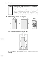
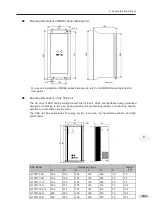
Page 25: ...542 300 275 10 35 Sheet metal housing GT600 4T55GB GT600 4T75GB 270 560 554 580 338 315 10 51 5 Sheet metal housing GT600 4T90G GT600 4T110G GT600 4T132G 320 705 704 745 400 310 10 85 Sheet metal hous...

Page 26: ...l Dimensions mm Weight kg Housing Type A A1 B B1 H H1 W W1 D D1 GT600 4T200G 240 150 1035 86 1086 1134 300 360 500 13 110 Sheet metal housing GT600 4T220G GT600 4T250G 240 185 1175 96 1238 1284 330 39...

Page 27: ...sions mm Weight Kg Housing Type A A1 B B1 H H1 W W1 D D1 GT600 4T200G L 240 150 1035 424 1424 1472 300 360 500 13 160 Sheet metal housing GT600 4T220G L GT600 4T250G L 240 185 1175 435 1586 1622 330 3...

Page 28: ...AC drive can be then pushed into the cabinet and secured 2 4 1 Backplate Mounting The backplate mounting process is as follows 1 Select a suitable location See recommendations in CAUTION 2 Measure and...

Page 29: ...ounted installation of a plastic housing Figure 2 10 Backplate mounted installation of a sheet metal housing 2 4 2 Through Hole Mounting There are three steps in process of preparing a through hole mo...

Page 30: ...h hole mounting bracket installation for a sheet metal housing Ensure all screws and bolts that secure the brackets to the housing are tight Step 2 Preparing the Backplate for Hole Cut out Refer to to...

Page 31: ...kings you made in step 6 Prepare edges of the cut out to remove sharp edges and burrs Step 3 Installing the AC Drive into the Hole Cut out Lift the AC drive into the cut out you have prepared Insert t...

Page 32: ...dels Through hole Mounting Bracket Model Applicable AC Drive Model Bracket Dimensions GT600 AZJ A1T5 GT600 4T18 5GB Refer to GT600 4T22GB GT600 AZJ A1T6 GT600 4T30GB GT600 4T37GB GT600 AZJ A1T7 GT600...

Page 33: ...2 Effective area means through hole area 3 The specification is only applicable to single unit installation in cabinet For multi drive installation in cabinet contact Inovance for technical support Ca...

Page 34: ...586 31809 50894 GT600 4T220G L 2 722 31809 50894 GT600 4T250G L 3 789 47713 76341 GT600 4T280G L 3 882 47713 76341 GT600 4T315G L 3 644 47713 76341 GT600 4T355G L 3 796 47713 76341 GT600 4T400G L 3 7...

Page 35: ...nd pull out to ensure safety CAUTION Refer to Figure 2 3 for mounting clearance requirements Ensure there is sufficient space allow for efficient heat dissipation of the drive and the other devices in...

Page 36: ...minal of GT600 copper bar The cabinet dimension is 2200 x 800 x 600 mm The height 2200 mm includes the 200 mm cabinet ventilation top cover but does not include the 100 mm cabinet base After push in r...

Page 37: ...cure the fixing beam and reserve mounting holes The cross section of the nine folding AL cabinet is shown in the following figure Figure 2 15 Cross section of the nine folding AL cabinet Front door Wh...

Page 38: ...tall it at the bottom of the nine folding AL cabinet If a non nine folding AL cabinet is used drill mounting holes for the mounting bracket on site Figure 2 17 Installing the bottom mounting bracket N...

Page 39: ...inet Remove the front cover from the drive referto the handle is exposed Arrange two persons to align castors of the drive to the guide rail Figure 2 20 Align castors of the drive to the guide rail Th...

Page 40: ...ms on cabinet back Mounting bracket Guide rail optional Figure 2 22 Push in completed Fix the AC drive to the beams on the back of the cabinet as shown in the following figure Check that installation...

Page 41: ...n the cabinet Baffle of ventilation Please use top hoist rings to move or hoist the drive If it is necessary to place the drive in a horizontal position use the top hoist ring and bottom hoist hole wh...

Page 42: ...front cover to the drive and push it down in the arrow direction until the side latches are in place 1 Refitting 2 5 Remove and Refit the Front Cover You must remove the front cover before performing...

Page 43: ...oval Loosen four screws from the front cover and then remove the front cover 2 Remove and Refit the Front cover of a Sheet Metal Housing Reattaching Locate and align the fixing hook at the top of the...

Page 44: ...and Refit the Front cover of GT600 4T200G L to GT600 4T450G L Removal Loosen six screws from the front cover and then remove the front cover Reattaching Locate and align the fixing hook at the top of...

Page 45: ...2 Mechanical Installation 43 3 Electrical Installation 3 1 Typical System Connection 44 3 2 Main Circuit Wiring 45 3 3 Control Circuit Wiring 61 3 4 Wiring Checklist 70...

Page 46: ...03 12 DI2 DI3 DI4 operation PE A1 B1 Encoder output pulses Multi Reference 2 F4 04 13 The DI5 supports a maximum of 100 kHz pulse input DI5 COM Jumper J7 AO1 J11 RJ45 for remote external operating pa...

Page 47: ...3 1 Description of input and output connections of the drive Terminal Name Description R S T Three phase supply input Connected to three phase power supply DC bus terminals Connected to external braki...

Page 48: ...lowed in a cable tray For North America the recommended cables in the preceding table must be copper wires rated 600 V 75 C Cable Dimensions and Tightening Torque Figure 3 1 Terminal dimensions of GT6...

Page 49: ...e of GT600 4T30GB GT600 4T37GB Figure 3 3 Terminal dimensions of GT600 4T45GB 55GB Table 3 4 Recommended cable dimensions and tightening torque of GT600 4T45GB GT600 4T55GB AC Drive Model Rated Input...

Page 50: ...put Current A Input Output Power Cable Crimp Terminal Model Ground Cable Crimp Terminal Model Tightening Torque N m Screw Spec GT600 4T75GB 139 3 x 70 mm2 3 x 2 0 AWG 70 12 35 mm2 4 AWG 22 12 35 0 M12...

Page 51: ...ive Model Rated Input Current A Power Input Output Cable Crimp Terminal Model Ground Cable Crimp Terminal Model Tightening Torque N m Screw Spec GT600 4T132G 240 3 x 150 mm2 350 kcmil 150 12 95 mm2 2...

Page 52: ...tor 236 5 85 50 2 13 48 5 31 5 60 69 Figure 3 7 Terminal dimensions of GT600 4T200G L 220G L with output reactor 236 5 85 0 2 13 31 5 108 5 108 5 174 33 33 33 102 5 W 122 5 V U 122 5 8 M12 315 5 118 5...

Page 53: ...inal dimensions of GT600 4T200G L 220G L without side entry copper bar without output reactor Table 3 7 Recommended cable dimensions and tightening torque of GT600 4T200G L 220G L AC Drive Model Rated...

Page 54: ...side entry copper bar without output reactor Table 3 8 Recommended cable dimensions and tightening torque of GT600 4T250G L and GT600 4T280G L AC Drive Model Rated Input Current A Power Input Output C...

Page 55: ...30 196 123 123 W V U 45 45 45 8 M16 118 111 130 130 398 50 Figure 3 12 Terminal dimensions of GT600 4T315G 450G without output reactor Figure 3 13 Terminal dimensions of GT600 4T315G L 450G L with out...

Page 56: ...able Crimp Terminal Model Ground Cable Crimp Terminal Model Tightening Torque N m Screw Spec GT600 4T315G L 565 2 x 3 x 185 mm2 500 kcmil x 2P 250 16 185 mm2 2 0 AWG 70 16 85 0 M16 GT600 4T355G L 617...

Page 57: ...49 7 20 7 18 0 15 5 11 4 2 0 YA 5 70 12 13 0 24 0 51 0 20 0 19 0 17 5 13 3 2 0 YPT 150 1 80 12 13 0 27 0 54 2 20 7 20 0 19 5 14 5 2 3 YPT 150 1 100 12 13 0 28 5 55 6 20 4 21 0 22 3 16 4 2 6 YPT 150 1...

Page 58: ...standards Install filter close to power input side of the AC drive with cable shorter than 30 cm Connect the ground terminal of filter and the ground terminal of the drive together to the cabinet main...

Page 59: ...circuit to the brake resistors Braking resistor terminals and PB are only for the drive units up to 75 kW that are fitted with an internal braking unit To avoid risk of equipment damage use a cable n...

Page 60: ...amps for the screen shield of the cables Installation of the bracket is shown below Table 3 13 Cable support bracket models Cable Support Bracket Model Applicable Drive Model GT600 AZJ A2T5 GT600 4T18...

Page 61: ...rtant to connect ground PE terminal to an effective electrical ground Resistance value of the ground cable must be less than 10 Do not connect the grounding PE terminal of the drive to neutral conduct...

Page 62: ...tection device on power input must be suitably rated for the power and voltage class of the drive under normal conditions and under possible fault conditions such as system overload and short circuit...

Page 63: ...voltage output by default AI2 input selection voltage input by default AI2 input impedance selection 500 by default 250 selectable 3 3 3 Control Circuit Wiring 3 3 1 Control Circuit Terminals Termina...

Page 64: ...nputs 0 to 10 VDC Input impedance 22 k AI2 GND Analog input 2 Either a voltage or a current input determined by jumper J9 Input voltage range 0 to 10 VDC Input current range 0 to 20 mA Input impedance...

Page 65: ...output Controlled by F5 00 FM terminal output selection Max output frequency 100 kHz When used as an open collector output the specification is the same as for DO1 Relay outputs T A T B Normally clos...

Page 66: ...electrical interference from the PWM effects of the motor cable Do not run motor cables power input cables and control wirings in the same duct to avoid electromagnetic interference caused by couplin...

Page 67: ...r from effects of severe external interference install a filter capacitor or a ferrite magnetic core at source of analog signal The pig tail of the shield must be connected to the PE terminal on the d...

Page 68: ...d wiring mode In this mode short terminals 24V and OP and connect COM to external power 0V To apply external 24V power supply remove the jumper between terminals 24V and OP and between terminals COM a...

Page 69: ...drive remove the jumper between terminals 24V and OP Connect 24V to the common port of external controller and connect terminal OP to terminal COM If you intend to use an external power supply remove...

Page 70: ...re 3 25 Wiring of digital output terminal Diode CAUTION Wiring of High speed Output FM When the FM terminal is used for continuous pulse output maximum output frequency is 100 kHz Figure 3 26 Wiring o...

Page 71: ...orbing circuit ordiode Figure 3 27 Wiring of relay 220 VAC 24 VDC Wire Size and Torque Specification Please use a ferrule type terminal with insulated sleeves Prepare wire ends with insulated sleeves...

Page 72: ...the U V W terminals of the drive properly 9 Check that cable diameter of main circuit complies with specification 10 Ground the AC drive properly 11 Check that output terminals and control signal ter...

Page 73: ...3 Electrical Installation 71 4 Operating Panel Keypad Display 4 1 Introduction 72 4 2 Inbuilt LED Operating Panel 72...

Page 74: ...n LED version with identical functions to the inbuilt version 4 2 Inbuilt LED Operating Panel The LED operating panel allows you to monitor system operation modify parameters and start or stop the AC...

Page 75: ...n RUNNING mode it decreases the speed Shift Select the displayed parameter in the STOP or RUNNING status Select the digit to be modified when modifying a parameter value RUN RUN Start the AC drive whe...

Page 76: ...ay 01 user defined parameters will display 10 user modified parameters will display 11 both of them will display 00 4 Relevant Parameters for Operating Panel Setting Status Indicators There are four r...

Page 77: ...g Hz A RPM V Hz for frequency Hz A RPM V A for current Hz A RPM V V for voltage Hz A RPM V RPM for motor speed Hz A RPM V Percentage LED Display The five digit LED data display can show the following...

Page 78: ...4 4 2 1 LED Operating Panel Menu Structure The drive operating panel has three levels of menu 1 Level I function parameter group 2 Level II function parameter 3 Level III function parameter value Figu...

Page 79: ...rn PRG ENTER Return PRG Level II menu PRG ENTER ENTER ENTER Level III menu Default screen 4 ENTER ENTER Return PRG ENTER Operation procedure of the three levels of menu is as follows The following exa...

Page 80: ...l III menus if the parameter does not include a flashing digit then it is not possible to modify that parameter There are two possible reasons for this 1 The function parameter you have selected is re...

Page 81: ...tandard function code group Standard function parameters A0 to AC Advanced function code group AI AO correction U0 to U3 RUNNING status function code group Display of basic parameters Selection of Fun...

Page 82: ...up to 30 function parameters to include into function group FE User modified quick view mode The function parameters that have been modified by a user are shown here Press to cycle through three funct...

Page 83: ...ction FE 13 F5 07 AO1 function selection FE 14 F6 00 Start mode FE 15 F6 10 Stop mode 4 The following table lists the often used parameters in the user defined menu Table 4 3 Often used parameters in...

Page 84: ...g panel Function Code Parameter Name Setting Range Default FP 01 Parameter initialization 0 No operation 0 1 Restore default settings except motor parameters 2 Clear records including errors 4 Back up...

Page 85: ...the user defined password 2 Make a written note of the value you have set for FP 00 and keep the note in a safe location 3 Press to exit the function parameter editing mode The password protection is...

Page 86: ...5 Quick Setup 5 1 Get Familiar With Operating Panel 86 5 2 Setup Flowchart 87...

Page 87: ......

Page 88: ...operating panel allows you to monitor system operation modify parameters and start or stop the AC drive Command sourceindicator Running statusindicator LED display forparameters Running direction indi...

Page 89: ...ecords including errors 4 Back up parameters 501 Restore user s backup parameters NOTE It is recommended to Restore default settings prior to commissioning the AC drive Set motor parameters Motor Name...

Page 90: ...th static while if choose 2 then motor will rotate so better disconnect load from motor shaft for safety Steps of auto tuning 1 Ensure the UVW connection between AC Drive and motor is not disconnected...

Page 91: ...Pulse setting DI5 6 Multi reference setting 7 Simple PLC 8 PID 9 Communication setting Set F0 08 F0 08 Preset frequency 50 00 If AI1 is frequency reference 0 Hz to F0 10 Set AI1 F4 13 AI curve 1 minim...

Page 92: ...cy reference 0 V to F4 25 F4 24 Corresponding percentage of AI3 minimum input 0 0 100 0 to 100 0 F4 25 AI3 maximum input 10 00 F4 23 to 10 00 V F4 26 Corresponding percentage of AI3 maximum input 100...

Page 93: ...ference terminal 2 14 Multi reference terminal 3 15 Multi reference terminal 4 16 Terminal 1 for acceleration deceleration time selection 17 Terminal 2 for acceleration deceleration time selection 18...

Page 94: ...hover 47 Emergency stop 48 External STOP terminal 2 49 Deceleration DC injection braking 50 Clear the current running time 51 59 Reserved Setting range 0 to 59 F4 01 DI2 function selection 4 Setting r...

Page 95: ...cy level detection FDT1 output 4 Frequency reached 5 Zero speed running no output at stop 6 Motor overload pre warning 7 AC drive overload pre warning 8 Set count value reached 9 Designated count valu...

Page 96: ...3 Reverse running 34 Zero current status 35 IGBT temperature reached 36 Software current limit exceeded 37 Frequency lower limit reached having output at stop 38 Alarm output 39 Motor overheat warning...

Page 97: ...function F5 07 AO1 function selection 0 Setting range same as F5 06 F5 08 AO2 function selection 1 Setting range same as F5 06 AO2 is on extension card Set accel decel time F0 17 Acceleration time 1 m...

Page 98: ...torque boost 50 00 0 00 Hz to maximum output frequency F3 03 Multi point V F frequency 1 0 00 0 00 Hz to F3 05 F3 04 Multi point V F voltage 1 0 0 0 0 to 100 0 V F3 05 Multi point V F frequency 2 0 0...

Page 99: ...portional gain 1 30 To achieve better performance 0 to 100 F2 01 Speed loop integral time 1 0 5 0 01 to 10 00 Sec F2 02 Switchover frequency 1 5 00 0 00Hz to F2 05 F2 03 Speed loop proportional gain 2...

Page 100: ...5 Quick Setup 98 5...

Page 101: ...ce 100 6 2 Set Frequency Reference 108 6 3 Start Stop the AC Drive 135 6 4 Motor Auto tuning 142 6 5 Control Performance 146 6 6 Protections 157 6 7 Monitoring 165 6 8 Process Control 172 6 9 Control...

Page 102: ...he RUN commands are given by pressing keys and STOP on the operatingpanel Press Press to start the AC Drive to stop the AC Drive For details on operating panel refer to F0 02 1 Terminal I O control Th...

Page 103: ...I Three wire Three wire control mode 1 control mode 2 REV DI Run enabled DI Stop DI Direction DI COM COM F4 11 AI1 F0 02 Serial communication 6 1 1 Terminal I O Control F4 11 defines the four terminal...

Page 104: ...ow Function Code Parameter Name Value Function Description F0 02 Command source selection 1 Terminal I O control F4 11 Terminal I O control mode 0 Two wire control mode 1 F4 00 DI1 function selection...

Page 105: ...command SW2 reverse run command Motor rotates in Stop reverse direction Stop Motor rotaes in forward direction Motor speed SW2 reverse run command SW1 forward run command 6 Sequence diagrams of two wi...

Page 106: ...ning direction The parameters are set as below Function Code Parameter Name Value Function Description F0 02 Command source selection 1 Terminal I O control F4 11 Terminal I O control mode 1 Two wire...

Page 107: ...verse RUN REV F4 01 DI3 function selection 3 Three wire control SW3 is a normally closed button and SW1 and SW2 are normally open buttons SW3 must remain closed during START sequence and during normal...

Page 108: ...tion 2 Reverse RUN REV F4 01 DI2 function selection 3 Three wire control SW3 is a normally closed button and SW1 and SW2 are normally open buttons SW3 must remain closed during start sequence and duri...

Page 109: ...AC drive Here takes the Modbus protocol as an example to describe process of giving run command via communication Figure 6 11 Example below with Modbus serial comms Function Code Parameter Name Fd 00...

Page 110: ...l 6 2 1 Set Main Frequency Reference Main frequency reference has nine setting channels F0 03 selects a required channel to set the main frequency reference described in the following figure Function...

Page 111: ...erial comms Fd 00 to Fd 05 Group FA Group FC Any of F4 00 to F4 09 39 Switchover between main frequency reference and preset frequency DI10 DI1 F4 00 to F4 04 12 13 14 15 FC 00 to FC 15 Set 16 frequen...

Page 112: ...ial value of frequency reference is F0 08 Preset frequency You can change frequency reference by pressing and on the operating panel or using the UP DOWN function of input terminals When the AC drive...

Page 113: ...u can set curves via parameters F4 13 to F4 27 and parameters in group A6 and select curves for AI1 AI2 and AI3 in F4 33 Here takes AI curve 1 as an example to describe how to set AI curve AI curve 1...

Page 114: ...er Name Setting Range Default F4 18 AI curve 2 min input 0 00 V to F4 20 0 00 V F4 19 Corresponding percentage of AI curve 2 min input 100 00 to 100 0 0 0 F4 20 AI2 curve max input F4 18 to 10 00 V 10...

Page 115: ...ut 100 0 to 100 0 0 0 A6 02 AI curve 4 inflexion 1 input A6 00 to A6 04 3 00 V A6 03 Corresponding percentage of AI curve 4 inflexion 1 input 100 0 to 100 0 30 0 A6 04 AI curve 4 inflexion 1 input A6...

Page 116: ...rve 3 2 points see to Curve 4 4 points see to Curve 5 4 points see to 321 Units position AI1 curve selection Tens position AI2 curve selection Hundreds position AI3 curve selection F4 17 AI1 filter ti...

Page 117: ...o 10 V corresponds to 20 0 to 100 0 100 0 corresponds to max frequency F0 10 50 00 Hz Select main frequency reference as final frequency reference F0 07 units position 0 F0 03 4 F4 33 hundreds positio...

Page 118: ...ency reference is input by means of DI5 high speed pulse Signal specification of pulse reference is 9 to 30 V voltage range and 0 to 100 kHz frequency range The corresponding value 100 of pulse refere...

Page 119: ...Reference 11 100 0 to 100 0 0 0 FC 12 Reference 12 100 0 to 100 0 0 0 FC 13 Reference 13 100 0 to 100 0 0 0 FC 14 Reference 14 100 0 to 100 0 0 0 FC 15 Reference 15 100 0 to 100 0 0 0 6 Multi referenc...

Page 120: ...F ON OFF ON Reference 5 FC 05 OFF ON ON OFF Reference 6 FC 06 OFF ON ON ON Reference 7 FC 07 ON OFF OFF OFF Reference 8 FC 08 ON OFF OFF ON Reference 9 FC 09 ON OFF ON OFF Reference 10 FC 10 ON OFF ON...

Page 121: ...5s h 0 0s h FC 27 Acceleration deceleration time of simple PLC reference 4 0 to 3 0 FC 28 Running time of simple PLC reference 5 0 0s h to 6553 5s h 0 0s h FC 29 Acceleration deceleration time of simp...

Page 122: ...C running mode 0 Stop after running one cycle 1 Keep final values after running one cycle 2 Repeat after running one cycle 0 FC 16 0 Stop after running one cycle The AC drive stops after running one c...

Page 123: ...Reference The PID Proportional Integral Derivative function uses system feedback for closed loop control of variables such as flow pressure temperature and so on The purpose of PID control is to keep...

Page 124: ...Any of F4 00 to F4 09 set for function 22 PID disabled or PID deviation smaller than FA 09 PID error limit 0 1 2 3 4 5 6 7 8 AI1 AI2 AI3 AI1 AI2 Pulse reference FA 08 in reverse direction Switchover...

Page 125: ...nsional parameter and is used for calculating display of PID reference U0 15 and PID feedback U0 16 U0 15 PID reference percentage x FA 04 U0 16 PID feedback percentage x FA 04 For example if FA 04 is...

Page 126: ...Code Parameter Name Setting Range Default FA 10 PID differential limit 0 00 to 100 00 0 10 FA 10 applies a limit to PID differential output as a large output can cause excessive system oscillation Fun...

Page 127: ...of PID parameters may be required to fine tune the overall performance as load conditions can vary during the different machine cycles Switchover can be implemented via a DI terminal or automatically...

Page 128: ...gain and derivative time take effect If integral separation is disabled no matter whether the DI set for function 38 PID integral disabled is on integral separation is inactive Function Code Parameter...

Page 129: ...me Setting Range Default F0 28 Serial port communication protocol 0 Modbus protocol 1 PROFIBUS DP protocol or CANopen protocol 0 When the AC drive is controlled via serial communication the host compu...

Page 130: ...rence to 10000 host computer sends write command 01 06 10 00 27 10 97 36 hexadecimal In the command 01H settable AC drive address 06H write command 1000H frequency reference address 2710H frequency re...

Page 131: ...s F0 04 selects a proper channel to set auxiliary frequency reference Function Code Parameter Name Setting Range Default F0 04 Auxiliary frequency reference setting channel selection 0 Digital setting...

Page 132: ...mms Fd 00 to Fd 05 Group FA Group FC Any of F4 00 to F4 09 40 Switchover between auxiliary frequency reference and preset frequency DI10 DI1 F4 00 to F4 04 12 13 14 15 FC 00 to FC 15 Set 16 frequency...

Page 133: ...erial comms F0 03 Mainfrequency setting channel Main 6 6 2 3 Main Auxiliary Calculation You can set relationship between final frequency reference and main frequency reference auxiliary frequency refe...

Page 134: ...quency reference is set by main and auxiliary calculation pay attention to the following aspects If auxiliary frequency reference is digital setting preset frequency F0 08 does not take effect You can...

Page 135: ...erence setting channel Figure 6 29 Command source main frequency reference setting channel Units position 0 1 9 Tens position 0 0 0 Hundreds position 0 0 0 Setting 000 001 009 Output 0 1 9 When a comm...

Page 136: ...ference lower limit 0 00 Hz to frequency upper limit F0 12 0 00 Hz F0 12 The motor is not allowed to run at frequency reference above the setting in this function parameter F0 14 The motor is not allo...

Page 137: ...F6 03 Start frequency 0 00 to 10 00 Hz 0 00 Hz F6 04 Start frequency holding time 0 0s to 100 0s 0 0s F6 05 DC injection braking 1 level Pre excitation level 0 to 100 50 F6 06 DC injection braking 1 a...

Page 138: ...he DC injection braking function is applicable to drive load such as elevator and crane as shown in Figure 6 30 3 Figure 6 30 1 Sequence of direct start Output frequency RUN command Acceleration time...

Page 139: ...Accelerate F6 00 2 Pre excited Start Motor speed tracking time It is valid only for asynchronous motor and used for building magnetic field before motor running For pre excited current and pre excited...

Page 140: ...s 0 0s F6 11 The AC drive starts DC injection braking when the running frequency decreases to the value set in this parameter in the process of deceleration to stop F6 12 When the running frequency de...

Page 141: ...braking 2 delay time F6 10 0 Decelerate to Stop Once the stop command is input the AC drive decreases the output frequency based on the deceleration time to 0 Figure 6 33 Decelerate to stop Output fre...

Page 142: ...ation time for selection You can perform switchover by using a DI terminal Group 1 F0 17 F0 18 Group 2 F8 03 F8 04 Group 3 F8 05 F8 06 Group 4 F8 07 F8 08 For example select DI7 and DI8 for switchover...

Page 143: ...e acceleration deceleration 0 F6 08 Time proportion of S curve start segment 0 0 to 100 0 F6 09 30 0 F6 09 Time proportion of S curve end segment 0 0 to 100 0 F6 08 30 0 6 The function parameters rela...

Page 144: ...rs F1 06 to F1 08 are obtained 6 6 4 Motor Auto tuning You can obtain parameters of controlled motor through motor auto tuning Motor auto tuning methods are static auto tuning 1 static auto tuning 2 a...

Page 145: ...If motor has constant output characteristic and is used for high accuracy application disconnect motor from load and use dynamic auto tuning It is applicable to SVC or FVC mode The dynamic auto tuning...

Page 146: ...requency asynchronous motor 1 F1 01 Rated motor power 0 1 to 1000 0 kW Model dependent F1 02 Rated motor voltage 1 to 2000 V Model dependent F1 03 Rated motor current 0 01 to 655 35 A AC drive power 5...

Page 147: ...ental encoder and thus is valid for ABZ incremental encoder F1 28 0 F1 30 0 Forward Phase A is advanced of phase B for forward motor rotation Phase B is advanced of phase A for reverse motor rotation...

Page 148: ...Multi point V F voltage 1 0 0 to 100 0 0 0 F3 05 Multi point V F frequency 2 F3 03 to F3 07 0 00 Hz F3 06 Multi point V F voltage 2 0 0 to 100 0 0 0 F3 07 Multi point V F frequency 3 F3 05 to rated mo...

Page 149: ...three voltage points and frequency points must satisfy V1 V2 V3 f1 f2 f3 When you set F1 F3 03 F2 F3 05 and F3 F3 07 set F3 07 first then F3 05 and finally F3 03 3 Variable torque Square V F curve Fi...

Page 150: ...000 0s 0 0s F3 16 Voltage decline time of V F separation 0 0s to 1000 0s 0 0s F3 17 Stop mode selection for V F separation 0 Frequency and voltage declining to 0 independently 1 Frequency declining af...

Page 151: ...g will result in motor overheat and AC drive overcurrent On starting a heavy load and insufficient torque is experienced increase the torque boost in F3 01 Decrease this parameter on light loads to av...

Page 152: ...such as centrifuge where high running frequency and several times of field weakening are required and load inertia is large The current limit level above rated frequency fs fn x k x LimitCur fs runni...

Page 153: ...s Set F3 10 V F over excitation gain to 0 Otherwise too large current may occur during drive running Set F3 23 overvoltage suppression selection to 0 disabled Otherwise the deceleration time may becom...

Page 154: ...nning frequency is between F2 02 and F2 05 PI parameters are obtained from linear switchover between two groups of PI parameters as shown in Figure 9 2 Figure 6 43 Speed loop PI parameters PIparameter...

Page 155: ...ng Range Default A0 00 Speed Torque control selection 0 Speed control 1 Torque control 0 This function parameter determines whether the AC drive is in speed control or torque control The AC drive has...

Page 156: ...nguished The torque limit is defined by F2 10 When F2 11 is set to 1 to 8 the motoring state and regenerative state are distinguished In motoring state full range of torque limit is set by F2 010 In r...

Page 157: ...set maximum frequency of the AC drive in forward and reverse directions in torque control Motor speed will rise continuously if load torque is smaller than motor output torque This function limits mo...

Page 158: ...ng area Be aware that this may lead to an increase in motor current ripple and an increase in motor heating Decreasing it will reduce motor current ripple and motor heating Be aware that this will low...

Page 159: ...ion has an inverse load time characteristics If the motor overload current level and overload protection time need be adjusted modify setting of F9 01 The inverse load time characteristic is shown in...

Page 160: ...otor current and motor runs at this level for 80 x 6 4 8 minutes DO terminal or fault relay outputs the motor overload pending signal When F9 02 100 the motor overload pending and the motor overload p...

Page 161: ...11 Delay of auto reset 0 1s to 100 0s 1 0s This function parameter sets the delay of auto reset after the AC drive detects a fault 6 6 4 Fault Protection Action Selection Function Code Parameter Name...

Page 162: ...3 Hundreds position Initial position fault Err51 Thousands position Speed feedback fault Err52 Ten thousands position Reserved These function parameters set action mode of the AC drive at occurrence o...

Page 163: ...es the value set in F9 58 digital output terminal set for function 39 becomes on The drive supports both PT100 and PT1000 Make sure to set sensor type correctly You can view motor temperature in U0 34...

Page 164: ...d 1 Bus voltage constant control 2 Decelerate to stop 0 F9 60 Threshold of power dip ride through function disabled 85 to 120 85 F9 61 Judging time of bus voltage recovering from power dip 0 1s to 10...

Page 165: ...Detection level of speed error 0 0 to 50 0 max frequency 20 0 F9 70 Detection time of speed error 0 0s to 60 0s 5 0s This function is effective only for vector control with speed sensor When detected...

Page 166: ...0 00s to 600 00s 0 00s 6 6 6 11 Output Overcurrent Protection This is to provide overcurrent protection for the AC drive If the drive s output current is equal to or smaller than the value set in F8...

Page 167: ...7 03 Binary 1 0 0 0 0 0 0 0 0 0 1 1 1 1 0 1 Hexadecimal 8 0 3 D Press the key on the operation panel The operation panel displays Press the key twice on the operation panel The display of the operatio...

Page 168: ...ng running set corresponding bit to 1 and set F7 03 to hexadecimal equivalent 1F F7 04 LED display running parameters 2 0000 to FFFF 7 6 5 4 3 2 1 0 PID feedback PLC stage Pulse reference kHz Running...

Page 169: ...meter needs to be displayed during running set corresponding bit to 1 and set F7 05 to hexadecimal equivalent 1F View Parameters in Group U0 You can view parameter values by using operation panel conv...

Page 170: ...h bit corresponds to a DO 1 indicates high level signal and 0 indicates low level signal The corresponding relationship between bits and DOs is described in the following table Bit0 Bit1 Bit2 Bit3 Bit...

Page 171: ...Range U0 24 Motor speed 0 to rated motor speed U0 24 It displays linear speed of DI5 used for high speed pulse sampling The unit is meter minute Linear speed is obtained according to actual number of...

Page 172: ...paration 0 V to rated motor voltage U0 39 and U0 40 They display target output voltage and current actual output voltage in V F separation status Function Code Parameter Name Display Range U0 41 DI st...

Page 173: ...rotates one revolution forwardly or reversely You can check whether installation of encoder is normal by viewing U0 58 Function Code Parameter Name Display Range U0 59 Frequency Reference 100 00 to 10...

Page 174: ...plications It indicates output frequency wobbles up and down with frequency reference as center Figure 6 48 Application of the wobble function Function Code Parameter Name Fb 01 Wobble amplitude Fb 02...

Page 175: ...gular wave rising time coefficient 0 0 to 100 0 50 0 Fb 03 It specifies time of a complete wobble cycle Fb 04 It is percentage of triangular wave rising time to Fb 03 Wobble cycle Triangular wave risi...

Page 176: ...o F4 09 DIx function selection 28 Length reset Any of F5 00 to F5 05 DOx function selection 10 Length reached 6 8 3 Counting The drive has the counting function The sampling DI terminal must be set fo...

Page 177: ...tputs the designated count value reached signal Clear to 0 Reset U0 12 Count value DIx DO outputs the set count value reached signal Compare Any of F4 04 Allocate DIx with the to F4 09 25 counter inpu...

Page 178: ...rameters respectively Set parameters related to V F control or vector control independently Motor 2 parameters are defined the same as motor 1 parameters For details on motor 1 parameters see descript...

Page 179: ...F1 03 AC drive power 55 kW 0 1 to F1 03 AC drive power 55 kW Auto tuning parameter A2 27 Encoder pulses per revolution 1 to 65535 1024 A2 28 Encoder type 0 to 2 0 A2 29 Speed feedback PG selection 0 t...

Page 180: ...rol See details in group F5 AC drive control See details in group F5 AC drive control See details in group F5 AC drive control See details in group F5 Figure 6 53 User programmable function 2 Figure 6...

Page 181: ...A7 00 User programmable function selection 0 Disabled 1 Enabled 0 2 Set AI3 and AO2 function on user programmable card The user programmable card provides an analog input terminal AI3 and an analog ou...

Page 182: ...digital output 000 to 111 0 Disabled 1 Enabled 000 Units position FMR Tens position Relay Hundreds position DO1 The base value of A7 03 is F5 09 Max FMP output frequency The base value of A7 04 is 10...

Page 183: ...ogrammable card is enabled torque reference of the AC drive is determined by setting of A7 07 You can implement control of torque reference of AC drive via PLC program by operating corresponding D com...

Page 184: ...flexibly the slaves must work in speed control because slight speed difference amongst AC drives is allowed When master and slaves are in speed control droop rate must be used Figure 6 55 Rigid Flexib...

Page 185: ...t in speed control mode 0 0 to 200 0 130 0 You can use a relay for slave fault feedback or set tens position of A8 02 to 1 to send the salve fault information to the master via communication Then when...

Page 186: ...ds position whether to alarm when it becomes off line A8 03 The slave received data 0 Output frequency 1 Frequency reference 0 A8 11 Window width 0 20 to 10 00 Hz 0 5 Hz F0 10 Max frequency 5 00 to 50...

Page 187: ...Set by A0 03 1 AI1 2 AI2 3 AI3 4 Pulse reference DI5 5 Serial comms 6 MIN AI1 AI2 7 MAX AI1 AI2 0 A0 03 Torque digital setting in torque control 200 0 to 200 0 130 0 A0 07 Acceleration time in torque...

Page 188: ...he same setting of this parameter for the master and slave F8 15 Droop rate 0 00 to 10 00 Hz 1 00 Hz F0 17 Acceleration time 1 0 0 to 6500 0s Keep the same setting of this parameter for the master and...

Page 189: ...inal I O control 2 Serial comms 2 F0 03 Main frequency reference setting channel selection 0 Digital setting non retentive at power down 1 Digital setting retentive at power down 2 AI1 3 AI2 4 AI3 5 P...

Page 190: ...quency is 50 Hz and output torque is 50 Actual drive frequency 50 Hz 50 x 50 x 1 00 10 47 5 Hz This function parameter determines whether to enable point point communication The point point communicat...

Page 191: ...o droop control or speed synchronization control slave in speed control In load sharing control slave in torque control the master sends its output frequency to the slave In this case ensure F8 15 0 A...

Page 192: ...n panel Remote fault reset is implemented by this function 10 RUN disabled When the terminal set for this function becomes on the AC drive decelerates to stop and retains all running parameters such a...

Page 193: ...s used to perform switchover between communication control and operation panel control 21 Acceleration Deceleration prohibited This function ensures the AC drive to maintain current frequency output w...

Page 194: ...cy set in F0 08 41 Motor selection Switchover between motor 1 and motor 2 can be implemented through two state combinations of terminal set for this function 42 Reserved 43 PID parameter switchover If...

Page 195: ...ction enables the AC drive to switch over between two wire control and three wire control If F4 11 is set to two wire control mode 1 the AC drive switches over to three wire control mode 1 when termin...

Page 196: ...P A P B P C is the relay on the I O extension card The functions of the digital output terminals are described in the following figure Value Function Description 0 No output Terminal has no function 1...

Page 197: ...When running frequency reaches frequency lower limit terminal set for this function becomes on When the AC drive is in stop status terminal set for this function becomes off 19 Undervoltage Terminal...

Page 198: ...an alarm signal 39 Motor overheat pending Terminal set for this function becomes on when motor temperature reaches value set in F9 58 Motor overheat pending threshold You can view motor temperature by...

Page 199: ...9 0 A1 01 VDI2 function selection 0 to 59 0 A1 02 VDI3 function selection 0 to 59 0 A1 03 VDI4 function selection 0 to 59 0 A1 04 VDI5 function selection 0 to 59 0 These function parameters set functi...

Page 200: ...gether with VDIx to implement some simple logic control Function Code Parameter Name Setting Range Default A1 11 VDO1 function selection 0 Short with physical DIx internally 1 to 40 0 A1 12 VDO2 funct...

Page 201: ...ctive 000 Units position AI1 Tens position AI2 Hundreds position AI3 6 6 9 5 Function of the AI Terminals The drive provides two AI terminals AI1 AI2 An extra AI terminal AI3 is provided by I O extens...

Page 202: ...sponding to 0 0 to 100 0 of Pulse or Analog Output Range 0 Running frequency 0 to max frequency 1 Frequency reference 0 to max frequency 2 Output current 0 to 2 times of rated motor current 3 Output t...

Page 203: ...orresponds to 10 V or 20 mA You can calculate the gain and the zero offset coefficient from the following formulas K Y1 Y2 x Xmax X1 X2 x Ymax X1 xY2 X2 x Y1 b X1 X2 x Ymax In the formulas b represent...

Page 204: ...n parameters correctly Otherwise communication may fail 6 10 1 Read and Write Function Parameters 202 Read Function Parameters For function parameters in groups F0 to FF and A0 to AF the highest eight...

Page 205: ...r to EEPROM while the lowest eight bits indicate the hexadecimal number converted from SN in function code group For example host computer writes data to F0 16 If not writing to EEPROM communication a...

Page 206: ...as an example to describe communication process of host computer to read drive running status First set F0 28 1 to select CANopen protocol Suppose that DIP setting of Node ID of the AC drive is 0x05...

Page 207: ...TA7 Data 4 Reserved 6 Sending message format of read operation is described as follows CAN CANopen Data Description 11 bit ID 0x600 Node ID The Node ID of the equipment is set via the DIP switch RTR 0...

Page 208: ...s RUN Command Description 2000H 1 Forward run 2 Reverse run 3 Forward jog 4 Reverse jog 5 Coast to stop 6 Decelerate to stop 7 Fault reset Here takes CANlink protocol as an example to describe communi...

Page 209: ...n 1000 binary Q A sign 1 binary Q A sign 1 binary Command code 05H Command code 05H Target address 02H Target address 01H Source address 01H Source address 02H Data length 4 decimal Data length 4 deci...

Page 210: ...requency reference in write command is 1F40H converted to decimal 8000 frequency reference that is written is 50 x 80 00 40 Hz 6 6 10 4 Write Frequency Torque Reference You can set frequency reference...

Page 211: ...Analog and High speed Pulse Output AO FMR When F5 06 F5 07 or F5 08 12 you can control analog and high speed pulse output by using host computer The communication address and command of analog and hig...

Page 212: ...function If this function is enabled and any of F4 00 to F4 09 is set to 4 forward jog or 5 reverse jog becomes active the AC drive enters jog running status immediately Figure 6 59 Jog running Output...

Page 213: ...celeration the AC drive runs for a period at current frequency reference and then jumps over jump frequency The jump width is twice of F8 11 When running frequency decelerates to the value close jump...

Page 214: ...un Dead zone time Reverse run Function Code Parameter Name Setting Range Default F8 12 Forward Reverse run switchover dead zone time 0 0s to 3000 0s 0 0s Reverse Run Prohibited Figure 6 62 Control of...

Page 215: ...Hz F8 20 Frequency detection hysteresis 1 0 0 to 100 0 5 0 F8 28 Frequency detection value 2 0 00 Hz to max frequency 50 00 Hz F8 29 Frequency detection hysteresis 2 0 0 to 100 0 5 0 F8 19 It sets de...

Page 216: ...ange during drive running This function is active only when motor 1 is selected and acceleration deceleration time is not switched over via external DI terminal Figure 6 65 Acceleration Deceleration t...

Page 217: ...uency detection signal DO or relay OFF OFF The drive provides two groups of frequency detection parameters for the digital output functions 26 and 27 When the output frequency is in the range of the d...

Page 218: ...t 0 0 F8 40 Detection level of current 2 0 0 to 300 0 rated motor current 100 0 F8 41 Detection width of current 2 0 0 to 300 0 rated motor current 0 0 6 11 9 Timing Function Function Code Parameter N...

Page 219: ...es the value set in F8 47 digital output terminal set for function 35 becomes on 6 11 12 Cooling Fan Function Code Parameter Name Setting Range Default F8 48 Cooling fan working mode 0 Working during...

Page 220: ...of PID operation at stop 6 11 14 Running Time Threshold This Time Function Code Parameter Name Setting Range Default F8 53 Running time threshold this time 0 0 to 6500 0 min 0 0 min If running time t...

Page 221: ...Interfaces and Communication 7 1 About Use of GT600 Terminals 220 7 2 Serial Communication 223 7 3 About Multi functional Extension Interfaces 224 7 4 Definition of Communication Data Address 225 7 5...

Page 222: ...terminals Filter Time and Delay Functions F410 sets a filter time on the DI signal to improve performance of the drive in conditions of strong electrical interference The drive also provides a signal...

Page 223: ...erminal is high speed pulse output Frequency of pulses on this DO terminal indicates the value of internal running parameters Higher values of internal running parameters produce higher pulse frequenc...

Page 224: ...to improve stability and accuracy of motor speed control In this case it is necessary to install an encoder on motor to provide sensor input to PG card that the drive requires There are four versions...

Page 225: ...ware communication parameters for the relevant communication protocol You must set identical communication rate and data format for the drive and for the host computer otherwise communications will fa...

Page 226: ...lable for all models Resolver interface card GT60PG4 For use with a resolver that has an excitation frequency of 10 kHz The card has a DB9 interface Available for all models Open collector encoder int...

Page 227: ...and A0 to AF the high 16 bits of the communication address indicate the group number and the low 16 bits indicate the parameter number in the group Example Communication address of F0 16 is F010H wher...

Page 228: ...urrent fault code of the AC drive by reading the address 3 AC drive running status When the drive running status is read via communication the communication address is 3000H You can obtain current run...

Page 229: ...s of Drive Running Status Status Definition 2001H BIT0 DO1 output control BIT1 DO2 output control BIT2 Relay1 output control BIT3 Relay2 output control BIT4 FMR output control BIT5 VDO1 BIT6 VDO2 BIT7...

Page 230: ...n HMI and initiates communication to perform parameter read or write operations on slaves The other devices slaves provide data to respond to query or operations from the master At the same moment eit...

Page 231: ...Frame of writing command from the master 3 5 byte 1 byte 1 byte 2 byte 2 byte 2 byte Frame of writing response from the slave If the slave detects a communication frame error or reading writing failu...

Page 232: ...mmand During transmission low order bytes follow the high order bytes Function code address L Number of function codes H It is the number of function codes read by this frame If it is 1 it indicates t...

Page 233: ...nt in the register Then the result is shifted in the direction of the least significant bit LSB with a zero filled into the most significant bit MSB position The LSB is extracted and examined If the L...

Page 234: ...tention to setting range unit and description of parameters when modifying them Parameter Group Visited Address Parameter Address in RAM F0 to FE 0xF000 to 0xFEFF 0x0000 to 0x0EFF A0 to AC 0xA000 to 0...

Page 235: ...cy unit 0 01 kHz 1004 Output current 1014 Feedback speed unit 0 1Hz 1005 Output power 1015 Remaining running time 1006 Output torque 1016 AI1 voltage before correction 1007 Running speed 1017 AI2 volt...

Page 236: ...Power input phase loss 000D Power output phase loss 000E IGBT overheat 000F External fault 0010 Communication fault 7 Parameter lock password check If 8888H is returned it indicates that password chec...

Page 237: ...ost 001F PID feedback lost during running 0028 Fast current limit timeout 0029 Motor switchover error during running 002A Too large speed deviation 002B Motor over speed 002D Motor overheat 005A Incor...

Page 238: ...Default Fd 03 Response delay 0 to 20 ms 2 ms This parameter sets interval between AC drive completing receiving data and AC drive sending data to host computer If response delay is shorter than system...

Page 239: ...es and Communication 8 Peripherals and Options 8 1 MCCB Fuse and Contactor 241 8 2 Braking Unit and Braking Resistor 242 8 3 External Operating Panel 246 8 4 Extension Cards 247 8 5 Through hole Mount...

Page 240: ...rive because of static electricity Operating the motor at low speed lowers the cooling effect and increases the motor temperature which unless the output torque is significantly reduced may result in...

Page 241: ...Three phase AC power supply Moulded case circuit breaker MCCB or leakage breaker Fuse Electromagnetic contactor GT600 External operating panel GT32NKE1 RUN LOC AL R EMOT FED REV TUN E TC Hz A V RPM AC...

Page 242: ...higher harmonics of the AC drive input side and reduce external conduction and radiation interference Braking resistor Use braking resistor for the GB type model of 75 kW and below Dissipate regenerat...

Page 243: ...25 FWH 125B 80 100 GT600 4T45GB 150 FWH 150B 95 160 GT600 4T55GB 200 FWH 200B 115 160 GT600 4T75GB 250 FWH 250A 150 250 GT600 4T90G 275 FWH 275A 170 250 GT600 4T110G 325 FWH 325A 205 400 GT600 4T132G...

Page 244: ...stable braking U value varies with the system The 400 VAC power system usually selects 700 V braking voltage Pb refers to braking power Selection of Power of Braking Resistor In theory power of brakin...

Page 245: ...x 2 200 MDBU 200 C 2 19000 W 5 8 2 Input voltage 440 VAC 3 0 x 2 GT600 4T220G L 220 MDBU 200 B 2 21000 W 4 1 2 Input voltage 440 VAC 2 5 x 2 220 MDBU 200 C 2 21000 W 5 3 2 Input voltage 440 VAC 3 0 x...

Page 246: ...of 10s Default initial braking voltage is 760 V The preceding table is for a reference only You can select resistance and power of braking resistor based on actual needs Resistance must not be lower t...

Page 247: ...Dimensions of MDBU Series Braking Unit 187 192 120 2 6 2 6 120 Unit mm For use and installation of MDBU series braking unit refer to the MDBU Series Braking Unit User guide Mounting Dimensions of the...

Page 248: ...KE1 is the external operating panel applicable to the drive It adopts the LED display and has the same operation mode as the operating panel on the drive For details refer to The following figures sho...

Page 249: ...ion Cards The drive can implement field bus by connecting various extension cares It supports different types of encoders and user programming function This chapter describes installation and use of t...

Page 250: ...d MD38PG4 For use with a resolver that has an excitation frequency of 10 kHz The card has a DB9 interface Without frequency dividing function Available for all models Open collector encoder interface...

Page 251: ...o an external unit Generally used to supply DI DO terminals and external sensors Max output current 170 mA OP1 Digital input power terminal Connect to 24V by the jumper J8 by default When applying an...

Page 252: ...rrent range 0 to 20 mA Output current with resistance range 0 to 500 Digital output DO2 CME Digital output 2 Optically coupled isolation dual polarity open collector output Output voltage range 0 to 2...

Page 253: ...esistor OFF 1 2 S1 AI3 PT100 PT1000 selection AI3 1 2 3 set to ON ON 1 2 3 4 5 6 7 8 PT1000 4 5 6 set to ON ON 1 2 3 4 5 6 7 8 PT100 6 7 8 set to ON ON 1 2 3 4 5 6 7 8 8 Setting of jumpers takes top v...

Page 254: ...external sensors Max output current 170 mA OP2 Digital input power terminal It is not connected to power supply by default It can be connected either to external power or 24V according to the actual...

Page 255: ...thout modification GT60PC1 has the following I O terminals and communication interface Table 8 5 Terminal descriptions of the GT60PC1 Type Terminal Terminal Name Function Description Power supply 24V...

Page 256: ...stance 2 4 k Voltage range for inputs 9 to 30 V DI7 OP1 Digital input 7 DI8 OP1 Digital input 8 DI9 OP1 Digital input 9 DI10 OP1 Digital input 10 Analog output AO2 GND Analog output 2 Output voltage r...

Page 257: ...rent Meaning Voltage Setting Current J1 RS485 terminal resistor matching selection J7 Run Stop selection Matching the terminal resistor Not matching the terminal resistor Run Stop J8 OP1 connecting mo...

Page 258: ...speed CANlink bus It complies with CANlink bus standard CANlink is based on CAN bus and developed by K R It is an open communication protocol and equipments supporting this protocol can be connected...

Page 259: ...than 0 3 m Connect the reference ground of all nodes together 1 Self prepared single core cable 2 Twin core STP cable Run the twisted cable and cable connected to COM closely 3 Multi core twisted pair...

Page 260: ...status 2 The Heartbeat protocol with which slave detects current state to master regularly 3 The SDO that supports accelerated transmission mechanism only and transmits one function code two bytes 4 T...

Page 261: ...0 0 0 1 0 2 0 0 0 0 1 1 3 1 0 500Kbps 1 1 1 1 0 1 61 1 1 1Mbps 1 1 1 1 1 0 62 1 1 1 1 1 1 63 Indicators Table 8 12 Descriptions of indicators Indicator State Description PWR in red ON Power on is norm...

Page 262: ...ndard It helps to implement control of drive running and parameter setting through remote serial interface Table 8 13 Terminal descriptions of GT60TX1 Type Terminal Terminal Name Function Description...

Page 263: ...d cable to connect 485 and 485 Connect a matching terminal resistor of 120 respectively at both ends of the bus to prevent signal reflection The RS485 bus allows connection of a maximum of 128 nodes a...

Page 264: ...used connect twisted pair to 485 and 485 respectively and shield to CGND Shield can be connected to CGND only It must not be connected to ground Terminal wiring if node does not have CGND For nodes w...

Page 265: ...Isolation 5 V power ground 8 Extension PROFIBUS DP Card GT60DP2 GT60DP2 complying with international PROFIBUS field bus standard is designed to connect the drive to PROFIBUS DP bus This card can impro...

Page 266: ...een DP card and the master D2 in green DP card and drive communication indicator ON Communication between DP card and the drive is normal OFF Communication between DP card and the drive fails check th...

Page 267: ...set DIP switch properly The system PEs must be reliably grounded Length of communication cable between GT60DP2 and PROFIBUS DP master varies with different setting of baud rate of the master Restrict...

Page 268: ...able specification 26 to 16 AWG 0 1 to 1 3 mm2 Max frequency Differential 500 kHz Open collector 100 kHz Max frequency 100 kHz Frequency dividing coefficient 0 to 63 Frequency dividing coefficient 2 t...

Page 269: ...y 500 kHz Max frequency 500 kHz Excitation frequency 10 kHz Differential input limit 7 V Differential input limit 7 V Differential input limit 7 V User interface J7 J8 Oblique terminal block User inte...

Page 270: ...der power ground PE Shield connecting point J7 OA Differential frequency dividing output signal A positive OA Differential frequency dividing output signal A negative OB Differential frequency dividin...

Page 271: ...l processing quality indicator ON Signal is slightly instable which occurs when motor accelerates decelerates or interference during signal input is not completely filtered The number of interference...

Page 272: ...or State GT60PG4 Fault State Description D5 ON D6 ON Signal SIN COS amplitude too small Generally DB9 is not connected or wrongly connected or even wire breaks If the preceding conditions do not occur...

Page 273: ...der 15V 100mA power supply CCM Power ground and frequency dividing output ground COM Power ground and frequency dividing output ground A1 PG card frequency dividing output signal A OC output 0 to 24 V...

Page 274: ...put signal Z negative J7 J8 OA Frequency dividing output signal A positive OA Frequency dividing output signal A negative OB Frequency dividing output signal B positive OB Frequency dividing output si...

Page 275: ...PG card to complete the shield grounding To install PG card remove screw in amplified position and align mounting holes of PG card to the four fixing pins and fix PG card with the prepared M3 x 8 scr...

Page 276: ...size of GT600 4T18 5GB to GT600 4T22GB unit mm 5 5 4 M5 screw 4 243 232 Figure 8 2 Bracket dimensions and hole size of GT600 4T30GB to GT600 4T37GB unit mm 267 6 5 283 270 4 M6 screw 4 8 6 243 260 21...

Page 277: ...600 4T55GB unit mm 318 10 4 M7 screw 345 325 Figure 8 4 Bracket dimensions and hole size of GT600 4T75GB to GT600 4T110G unit mm 10 4 M8 screw 383 363 8 10 11 345 380 300 338 355 10 11 418 383 470 72...

Page 278: ...0 39 5 See details A 525 725 27 5 Note This DIN rail figure is applicable to the PS cabinet width 800 x depth 600 width 800 x depth 800 30 A Scale 1 1 Version Change mode Change order No Date Designed...

Page 279: ...ssed by Projection symbol Code 20180104 Scale Page 1 of 1 Standardized by Approved by 1 5 Product 35 5 38 35 5 38 580 780 32 5 9 42 5 22 5 2 FH M6 x 15 40 2 5 6 6 9 2 10 39 5 See details A 525 725 27...

Page 280: ...8 Peripherals and Options 278 8...

Page 281: ...8 Peripherals and Options 279 9 Maintenance and Inspection 9 1 Daily Inspection 280 9 2 Periodic Inspection 282 9 3 Replacement of Wearing Components 284 9 4 Storage 288 9 5 Warranty Agreement 288...

Page 282: ...form operations in accordance with instructions Tighten all terminal screws based on specified tightening torque Ensure that input voltage is within permissible range Incorrect input voltage of main c...

Page 283: ...k mechanical connections Check power phases of the motor Tighten all loose screws Fan Inspect whether the cooling fan of the AC drive and the motor works abnormally Check running of the drive side coo...

Page 284: ...nnections for discoloration Inspect wiring insulation for aging or wear Replace cracked cable Replace damaged terminals Peripheral devices such as relay and contactor Inspect contactors and relays for...

Page 285: ...strength test High voltage 500 V test need not be performed again because it has been completed before delivery VDR screw 2 1 9 2 2 Insulation Test on Main Circuit Figure 9 1 Test insulation on the m...

Page 286: ...hether there is liquid leakage Whether the safe valve has projected Measure the static capacitance Measure the insulation resistance The standard service time indicates the service time when the AC dr...

Page 287: ...n upward and disconnect the pluggable connector of power cable Fan power cable connector Look down from the back of the drive Installing 1 Plug in the fan power cable Fan power socket 2 Install the fa...

Page 288: ...he drive Fan power socket 2 Remove the four screws from the drive 3 Remove the fan and fan cover from the drive Fan cover Fan Fan power cable Installing 1 Align the mounting holes of the cooling fan f...

Page 289: ...e fan 1 2 4 3 Installing 1 Put the three fans into the fan box one by one and secure them by fixing the screws 2 Align the fan box to the rail and push it into the drive 3 Connect the fan power cable...

Page 290: ...e the input voltage gradually to rated value by using voltage regulator 9 5 Warranty Agreement 1 Free warranty only applies to the AC drive itself 2 K R will provide 18 month warranty from date of man...

Page 291: ...nspection 10 288 10 Troubleshooting 10 1 Safety Information 290 10 2 Troubleshooting During Trial Run 291 10 3 Fault Display 293 10 4 Resetting Fault 294 10 5 Faults and Diagnostics 295 10 6 Symptoms...

Page 292: ...e an enclosed cabinet use cooling fan or air conditioner to keep temperature below 50 C Failure to comply may result in overheating or even a fire Tighten all screws based on the specified tightening...

Page 293: ...by 0 05 gradually 2 If motor oscillation occurs decrease the setting of F2 00 and F2 01 Poor torque or speed response and motor oscillation at speeds above 5 Hz 1 If motor torque and speed response ar...

Page 294: ...oscillation occurs decrease the setting of F2 00 and F2 01 Poor torque or speed response and motor oscillation at speeds above 5 Hz 1 If motor torque and speed response are too slow increase the sett...

Page 295: ...selection is set to 1 enabled Increase the setting of F3 24 F3 25 frequency gain voltage gain for voltage limit by 10 gradually The permissible maximum setting here is 100 The default value of F3 22 i...

Page 296: ...Troubleshoot the fault according to section 11 5 Faults and Diagnostics Fault resetting method Fault resetting through a DI terminal Allocate a DI terminal with function 9 Fault reset RESET by setting...

Page 297: ...The AC drive suffers external interference View historical fault records If the current value is far from the overcurrent level find interference source If external interference does not exist it is...

Page 298: ...voltage during acceleration Cause Possible Solution Input voltage is too high Adjust input voltage to normal range An external force drives motor during acceleration Cancel the external force or insta...

Page 299: ...ontinuously Contact the agent or K R Operating Panel Display Fault Name Undervoltage Cause Possible Solution Instantaneous power failure occurs Enable the power dip ride through function F9 59 0 The A...

Page 300: ...otor is running Check whether the motor three phase winding is normal The drive board or the IGBT is abnormal Contact the agent or Inovance Operating Panel Display Fault Name IGBT overheat Cause Possi...

Page 301: ...ontactor The lightning protection board is abnormal Replace the lightning protection board Operating Panel Display Fault Name Current detection fault Cause Possible Solution The hall is abnormal Repla...

Page 302: ...Operating Panel Display Fault Name User defined fault 2 Cause Possible Solution User defined fault 2 is input via DI Reset the operation User defined fault 2 is input via virtual I O Reset the operat...

Page 303: ...Set F9 69 and F9 70 correctly based on actual condition Operating Panel Display Fault Name Motor overspeed Cause Possible Solution Encoder parameters are set improperly Set encoder parameters properly...

Page 304: ...e and 28 pin wire Related components on control board are damaged Contact the agent or K R The motor or motor cable is short circuited to ground The hall is damaged The mains voltage is too low Operat...

Page 305: ...external signal cables Jumper across OP and 24 V becomes loose Re confirm the jumper bar across OP and 24 V The control board is faulty Contact the agent or K R Operating Panel Display Fault Descripti...

Page 306: ...12 303 11...

Page 307: ...hooting 11 Appendix Appendix A Standards Compliance 306 A 1 CE Certification 306 A 2 UL Certification 329 Appendix B Parameter Table 330 B 1 Introduction 330 B 2 Standard Parameters 331 B 3 Monitoring...

Page 308: ...0 EU Electromagnetic compatibility Machines and devices used in combination with this drive must also be CE certified and marked The integrator who integrates the drive with the CE mark in into other...

Page 309: ...GT600 4T90G 275 FWH 275B GT600 4T110G 325 FWH 325B GT600 4T132G 400 FWH 400B GT600 4T160G 500 FWH 500B GT600 4T200G 600 FWH 600B GT600 4T220G 700 FWH 700B GT600 4T250G 800 FWH 800B GT600 4T280G 800 F...

Page 310: ...ent that includes domestic premises it also includes establishments directly connected without intermediate transformers to a low voltage power supply network which supplies buildings used for domesti...

Page 311: ...N3359 series filter Changzhou Jianli EBK5 Selection GT600 Model Input AC Filter Model Schaffner Input AC Filter Model Changzhou Jianli GT600 4T18 5GB FN 3258 55 34 DL 50EBK5 GT600 4T22GB FN 3258 75 34...

Page 312: ...0 20 4 5 1 22 M5 20 29 5 16 250 45 70 220 235 25 5 4 1 22 M5 22 5 29 5 30 270 50 85 240 255 30 5 4 1 25 M5 25 39 5 42 310 50 85 280 295 30 5 4 1 25 M6 25 37 5 55 250 85 90 220 235 60 5 4 1 39 M6 42 5...

Page 313: ...mpliance 12 311 H W Z V X Y 12 Dimensions of Schaffner FN 3270H series 150 2500A filter 150 to 250 A M A I D U U C O L J N K B Unit mm A I H F Unit mm Dimensions of copper bar 320 to 1000 A 311 G E E...

Page 314: ...70 250 F 185 185 205 235 235 235 255 255 275 330 G 12 12 12 12 12 12 12 12 12 14 H 2 2 2 2 2 2 3 3 3 3 I 33 33 33 43 43 43 53 53 93 98 J M10 M10 M10 M12 M12 M12 M12 M12 M12 M16 K 55 55 62 5 20 20 20 2...

Page 315: ...58 M4 74 49 M6 6 4 x 9 4 DL 35EBK5 DL 50EBK5 DL 65EBK5 DL 80EBK5 354 323 388 66 155 188 30 92 M8 62 M4 86 56 M8 6 4 x 9 4 DL 100EBK5 DL 130EBK5 DL 160EBK5 DL 200EBK5 Dimensions of the Jianli series 2...

Page 316: ...GT600 4T30GB GT600 4T37GB DL 120EB1 10 GT600 4T45GB GT600 4T55GB DL 180EB1 10 GT600 4T75GB GT600 4T90G to GT600 4T450G Unavailable Mounting Dimensions 6 5 0 2 Unit mm Simple EMC Filter Model Overall...

Page 317: ...ore to remove some interference during drive running Connect filter capacitance box to grounding terminal of the drive and ground cable length cannot exceed 300 mm Mounting dimensions of filter capaci...

Page 318: ...sted in the following table AC Drive Model AC Input Reactor Model K R GT600 4T18 5GB MD ACL 50 0 28 4T 2 GT600 4T22GB MD ACL 60 0 24 4T 2 GT600 4T30GB MD ACL 80 0 17 4T 2 GT600 4T37GB MD ACL 90 0 16 4...

Page 319: ...A are shown as below L Rated Current A B C D E F G H I J K L A mm 50 64 160 195 80 10 75 5 35 5 135 120 1 92 2 8 5 x 20 72 2 6 4 60 64 160 195 80 10 75 5 35 5 135 120 1 92 2 8 5 x 20 72 2 6 4 2 2 Vol...

Page 320: ...Dimensions of AC reactor of 150 to 330 A are shown as below A D C I K 318 E F G A R S T C X Y Z B H I J M K B B Z T Y S X R R E X F G H J M L Rated Current A B C D E F G H I J K L M A mm 150 250 81 5...

Page 321: ...50 23 660 320 106 5 305 145 10 203 5 50 5 240 243 1 12 x 20 137 2 12 22 50 23 Dimensions of AC reactor of 800 to 1000 A are shown as below A D H I K J N Rated Current A B C D E F G H I J K L M N A mm...

Page 322: ...200 to 500 135 22 200 to 500 150 30 280 to 690 150 AC Output Reactor Model Recommended AC output reactor manufacturer and models are listed in the following table AC Drive Model AC Output Reactor Mode...

Page 323: ...W B X Y Z C F G H Rated Current A B C D E F G H A mm 50 155 130 148 95 135 95 6 x 15 80 60 195 165 188 92 130 120 8 5 x 20 72 80 195 165 188 92 130 120 8 5 x 20 72 90 195 165 188 92 130 120 8 5 x 20...

Page 324: ...A mm 150 250 81 81 230 97 5 140 113 170 42 182 11 x 18 87 200 250 81 81 230 102 5 140 123 175 42 182 11 x 18 97 250 250 81 81 230 102 5 140 123 175 42 182 11 x 18 97 Dimension of AC output reactor of...

Page 325: ...6 1 GT600 4T37GB RWK 305 72 KL 72 37 0 082 70 KL 6 1 GT600 4T45GB RWK 305 90 KL 90 45 0 065 75 KL 7 4 GT600 4T55GB RWK 305 110 KL 110 55 0 053 90 KL 8 2 GT600 4T75GB RWK 305 156 KS 156 75 0 038 120 KS...

Page 326: ...8 x 12 10 mm2 60 and 72A 155 max 125 max 190 130 70 8 x 12 16 mm2 90A 190 max 115 max 225 170 57 8 x 12 35 mm2 110A 190 max 130 max 220 170 67 8 x 12 35 mm 2 124A 190 max 180 max 160 170 67 8 x 12 8...

Page 327: ...ve to reduce bearing current and reduce interference on surrounding devices The following figure shows installation of common mode filter The following figure shows physical appearance of ferrite core...

Page 328: ...ed should be as short as possible to reduce electromagnetic radiation and external stray current and capacitive current of the cable If motor cable is over 100 meters long an output filter or reactor...

Page 329: ...B type breaker must be used If multiple AC drives are required each AC drive must be installed with a circuit breaker Factors that influence the leakage current are as follows AC drive capacity Carrie...

Page 330: ...ng or when drive enabled take leakage current suppression measures install a leakage current filter install safety capacitor wind ferrite core AC drive interference during running Connect motor housin...

Page 331: ...If the AC drive has the cULus mark it indicates that the product complies with the following North Americal Standards Country Certification Name Standard U S UL UL508C Canada cUL C22 2 No 14 13 Note...

Page 332: ...unction parameters Group U includes the monitoring function parameters and extension card communication parameters The parameter description tables in this chapter use the following symbols The symbol...

Page 333: ...ction 0 1 0 F0 10 Max frequency 50 00 to 500 00 Hz 50 00 Hz F0 11 Setting channel of frequency upper limit 0 to 5 0 F0 12 Frequency reference upper limit Frequency lower limit F0 14 to max frequency F...

Page 334: ...5 A AC drive power 55 kW Model dependent F1 04 Rated motor frequency 0 01 Hz to max frequency Model dependent F1 05 Rated motor speed 1 to 65535 rpm Model dependent F1 06 Stator resistance 0 001 to 6...

Page 335: ...50 to 200 100 F2 07 Speed feedback filter time constant 0 000s to 0 100s 0 015s F2 09 Torque limit source in speed control 0 to 7 0 F2 10 Digital setting of torque limit in speed control 0 0 to 200 0...

Page 336: ...r excitation gain 0 to 200 64 F3 11 V F oscillation suppression gain 0 to 100 40 F3 13 Voltage source for V F separation 0 to 8 0 F3 14 Digital setting of voltage for V F separation 0 V to rated motor...

Page 337: ...00 00 to 100 0 0 0 F4 15 AI curve 1 max input F4 13 to 10 00 V 10 00 V F4 16 Corresponding percentage of AI curve 1 max input 100 00 to 100 0 100 0 F4 17 AI1 filter time 0 00s to 10 00s 0 10s F4 18 AI...

Page 338: ...000 to 11111 00000 Group F5 Output Terminals F5 00 FM terminal output mode 0 1 0 F5 01 FMR function selection 0 to 41 0 F5 02 Relay T A T B T C function selection 0 to 41 2 F5 03 Extension card relay...

Page 339: ...DC injection braking 1 level Pre excitation level 0 to 100 50 F6 06 DC injection braking 1 active time Pre excitation active time 0 0s to 100 0s 0 0s F6 07 Acceleration Deceleration mode 0 to 2 0 F6...

Page 340: ...ive running time 0 to 65535 h F7 10 Performance software version F7 11 Function software version F7 12 Number of decimal places for load speed display 10 to 23 21 F7 13 Accumulative power on time 0 to...

Page 341: ...cy of decel time 1 and decel time 2 0 00 Hz to max frequency 0 00 Hz F8 27 Set highest priority to terminal JOG function 0 1 0 F8 28 Frequency detection value 2 0 00 Hz to max frequency 50 00 Hz F8 29...

Page 342: ...tput power correction coefficient 0 0 to 200 0 100 0 F8 55 Deceleration time for emergency stop 0s to 6553 5s Model dependent Group F9 Fault and Protection F9 00 Motor overload protection 0 1 1 F9 01...

Page 343: ...ate upon 1st fault F9 43 Power on time upon 1st fault F9 44 Running time upon 1st fault F9 47 Fault protection action selection 1 00000 to 22222 00000 F9 48 Fault protection action selection 2 00000 t...

Page 344: ...reference setting channel 0 to 6 0 FA 01 PID digital setting 0 0 to 100 0 50 0 FA 02 PID feedback setting channel 0 to 8 0 FA 03 PID operation direction 0 1 0 FA 04 PID reference and feedback range 0...

Page 345: ...5 Set length 0 to 65535 m 1000 m Fb 06 Actual length 0 to 65535 m 0 m Fb 07 Number of pulses per meter 0 1 to 6553 5 100 0 Fb 08 Set count value 1 to 65535 1000 Fb 09 Designated count value 1 to 65535...

Page 346: ...ime of simple PLC reference 5 0 0s h to 6553 5s h 0 0s h FC 29 Acceleration deceleration time of simple PLC reference 5 0 to 3 0 FC 30 Running time of simple PLC reference 6 0 0s h to 6553 5s h 0 0s h...

Page 347: ...rmat symbol 0 to 3 0 Fd 02 Local address 0 Broadcast address 1 to 247 1 Fd 03 Response delay 0 to 20 ms 2 Fd 04 Communication timeout 0 0 invalid 0 1 s to 60 0s 0 0s Fd 05 Modbus protocol selection an...

Page 348: ...Same as FE 00 F0 00 FE 24 User defined parameter 24 Same as FE 00 F0 00 FE 25 User defined parameter 25 Same as FE 00 F0 00 FE 26 User defined parameter 26 Same as FE 00 F0 00 FE 27 User defined param...

Page 349: ...used as DI 0 to 59 0 A1 08 Function selection for AI2 used as DI 0 to 59 0 A1 09 Function selection for AI3 used as DI 0 to 59 0 A1 10 Active state selection for AI used as DI 000 to 111 000 A1 11 VDO...

Page 350: ...to A2 03 AC drive power 55 kW 0 1 A to A2 03 AC drive power 55 kW Auto tuning dependent A2 27 Encoder pulses per revolution 1 to 65535 1024 A2 28 Encoder type 0 ABZ incremental encoder 2 Resolver 0 A...

Page 351: ...to 60000 1300 A2 55 Speed loop integral separation selection 0 Disabled 1 Enabled 0 A2 59 Max torque coefficient in field weakening area 50 to 200 100 A2 60 Regenerative power limit selection 0 Disabl...

Page 352: ...percentage of AI curve 4 inflexion 2 input 100 0 to 100 0 60 0 A6 06 AI curve 4 max input A6 04 to 10 00 V 10 00 V A6 07 Corresponding percentage of AI curve 4 max input 100 0 to 100 0 100 0 A6 08 AI...

Page 353: ...program controlling digital output 000 to 111 000 A7 06 Setting frequency reference via the user programmable card 100 00 to 100 00 0 00 A7 07 Setting torque reference via the user programmable card...

Page 354: ...splayed voltage 2 10 00 to 10 000 V Factory corrected AC 08 AI3 measured voltage 1 10 00 to 10 000 V Factory corrected AC 09 AI3 displayed voltage 1 10 00 to 10 000 V Factory corrected AC 10 AI3 measu...

Page 355: ...length value U0 14 Load speed display 0 to 65535 U0 15 PID reference 0 to 65535 U0 16 PID feedback 0 to 65535 U0 17 PLC stage U0 18 Pulse reference 0 00 to 20 00 kHz U0 19 Feedback speed 500 0 to 500...

Page 356: ...5 U0 59 Frequency Reference 100 00 to 100 00 U0 60 Running frequency 100 00 to 100 00 U0 61 AC drive state 0 to 65535 U0 62 Current fault code 0 to 99 U0 63 Sending value of point point communication...

Page 357: ...e Compliance 306 CE Mark 306 Command Source Frequency Reference Setting Channe 133 Communication 202 Communication Data Address 225 Communication Parameter Addresses 232 Communication Parameter Descri...

Page 358: ...t on Main Circuit 283 Interfaces and Communication 220 Internal View of GT600 9 Introduction 72 Introduction 330 J Jog 210 Jump Frequency 211 L LED Operating Panel Menu Structure 76 Load Lost Protecti...

Page 359: ...Prevention 163 Overspeed Protection 163 P Parameter Data 225 Parameter Initialization 209 Parameter Table 330 Password Security 83 Periodic Inspection 282 Periodic Inspection Items 282 Peripheral Elec...

Page 360: ...Mode 135 Start the AC Drive 135 Start Stop Command Source 100 Stop Mode 138 Stop the AC Drive 135 Storage 288 SVC Speed Feedback Stability 153 SVC FVC Slip Compensation Gain 152 Symptoms and Diagnosti...

Page 361: ...00 4T200G L to GT600 4T450G L Firmware version F7 10 U76 57 F7 11 U77 57 Nov 2016 B01 Modified Approvals designation rule and nameplate Table 1 1 and Table 1 2 Nov 2018 B02 Updated K R s logo Apr 2020...

Page 362: ......

Reviews: