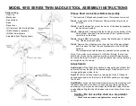
Please Read Instructions Before Assembly
** Tool required: Phillips head screwdriver or 12mm socket or wrench
Step 1
: Insert each of the 5 Casters or Glides into the outer holes on
the Base
.
Step 2
: Install the Base Cover over the center of the base by snapping
the two halves together.
Step 3
: (Models with Footring) Slide the Footring over the bottom of the
Gas Cylinder, then insert the bottom end of the Cylinder into the
center hole on the Base.
Step 4
: Using 4 M8x16mm screws, connect the Mechanism to the Seat
Top. Tighten screws securely.
Step 5
: Remove the protective cover from the top of the gas cylinder
and then place the Seat Top and Mechanism on top of the Gas
Cylinder.
The mechanism should be securely seated over the cylinder top.
Note: If you prefer your seat angle to tilt further forward, the two rear
M8x18mm screws can be removed and the optional M8 washers can
be inserted between the Seat Top and the Mechanism before replacing
and retightening the screws.
Adjustments:
Seat Height
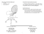
: Lift the Right lever handle to release the gas cylinder lock
and raise or lower the seat to the desired height. Release the lever to
re-engage the gas cylinder lock.
Seat Tilt
: Lift the Left lever handle to release the tilt lock. Tilt seat to
desired angle and return the lever to the DOWN position to re-engage
the tilt lock.
Seat Width:
Loosen the front Hand-wheel screw
counterclockwise
until
the seat halves can move freely. Loosen only enough to release the
seat halves. Do not over-loosen. Adjust the Width and Splay to the de-
sired setting and tighten the Hand-wheel screw
clockwise
. Do not over-
tighten
Caution: Do not use this chair as a step ladder.
Check for loose screws and tighten them every 6 months
1
Parts Listing
- Seat Top
- Mechanism
- Gas Cylinder
- Base
- Base Cover
- (5) Casters or Non-Rolling Glides
- (2) M8 Washers (optional)
- (4) M8x16mm Screws
- Adjustable Foot Ring (optional)
MODEL 901S SERIES TWIN SADDLE STOOL ASSEMBLY INSTRUCTIONS


