background image

GQRP / Kanga Regen construction manual V1.11 


Page 5 of 12 

Part 2. Power Supply 

Testing 


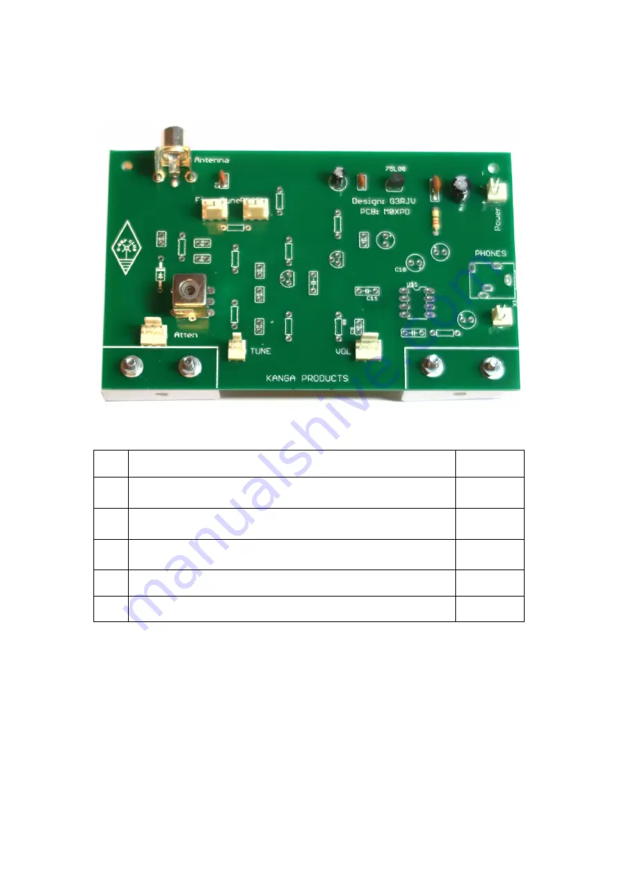
Your circuit should now look like this. 


Complete the following tests before moving onto the next stage. 


Test 

Complete 

Check over your soldering. Make sure all wires are trimmed, 

and no short circuits are present. 

q


Connect a 9v battery to the battery snap 

and connect the 

battery lead to the POWER Molex connector on the PCB


q


Measure between pins 6 and pin 4 of IC 

(G4) 

that you have 9 

Volts 

q


Measure across C1.

(B1)

 Ensure you have 8 Volts 

q


Disconnect the battery. 

q


Move onto Part 3 


Summary of Contents for URMSTON

Page 1: ...GQRP Kanga Regen construction manual V1 11 Page 1 of 12 The GQRP Regen Receiver Project Construction Instructions ...

Page 2: ...he negative and needs to be aligned with the on the circuit board The positive lead is a little longer too Headphone Socket Installing the headphone socket may require some tape to hold the component in place while soldering Use the tape to hold the socket while you make the 1st solder connection Potentiometers Wire each potentiometer in the same way as shown in the diagram LIN pots are marked wit...

Page 3: ...pprox 8cms and solder to FINE pot See Notes to the builder Cut Red Blue Green wire to approx 10cms and solder to REGEN pot See Notes to the builder Cut Red Blue Green wire to approx 6cms and solder to ATTEN pot See Notes to the builder q PCB C5 Tune Connection q q q q q q q See Notes to the builder I1 Power connection See Notes to the builder I4 Speaker connection See Notes to the builder A4 Atten...

Page 4: ...heck Orientation Solder in place q E1 Fit Capacitor Marked 10uF Solder in place See Notes to the builder Check Orientation q H1 Fit Capacitor Marked 100uF Solder in place See Notes to the builder Check Orientation q H1 Fit 100nF Capacitor Marked 104 Solder in place q F1 Fit 10nF Capacitor Marked 103 Solder in place q B1 Fit 10nF Capacitor Marked 103 Solder in place q A0 Antenna Socket See Notes to...

Page 5: ...e Test Complete 1 Check over your soldering Make sure all wires are trimmed and no short circuits are present q 2 Connect a 9v battery to the battery snap and connect the battery lead to the POWER Molex connector on the PCB q 3 Measure between pins 6 and pin 4 of IC G4 that you have 9 Volts q 4 Measure across C1 B1 Ensure you have 8 Volts q 5 Disconnect the battery q Move onto Part 3 ...

Page 6: ...it Capacitor Marked 10uF Solder in place See Notes to the builder Check Orientation q H4 Fit Capacitor Marked 100uF Solder in place See Notes to the builder Check Orientation q F2 Fit Capacitor Marked 10uF Solder in place See Notes to the builder Check Orientation q H2 Fit Capacitor Marked 100uF Solder in place See Notes to the builder Check Orientation q F3 Fit 100nF Capacitor Marked 104 Solder i...

Page 7: ...no short circuits are present q 2 Connect a 9v battery to the battery snap and connect the battery lead to the POWER Molex connector on the PCB q 3 Connect either headphones or a speaker to the PCB q 4 With a screwdriver touch the middle pin of the Molex connector marked VOL F5 Ensure you can hear a buzz q 5 Connect VOL connector from front panel and again touch middle pin q 6 Ensure the volume co...

Page 8: ... in place q A3 Fit IN4001 Check Orientation Solder in place q D3 Fit 2N3904 Centre pin bent back Check Orientation Solder in place q B3 Fit 10pF Capacitor Marked 10 or 10p Solder in place q B2 Fit 10nF Capacitor Marked 103 Solder in place q A2 Fit 10nF Capacitor Marked 103 Solder in place q C3 Fit 33pF Capacitor Marked 33 Solder in place q C3 Fit 330pF Capacitor Marked 331 Solder in place q C4 Fit...

Page 9: ...the circuit board and double check you have the right lead going to the right Molex plug socket q 3 Connect either a speaker or headphones q 4 Connect a wire antenna 60cms of wire will work q 5 Connect a 9v battery to the battery snap and connect the battery lead to the POWER Molex connector on the PCB q 6 Use the TUNE FINE to adjust the frequency of the radio and adjust the REGEN control to bring...

Page 10: ... here https www youtube com watch v LZuM3KOGkgg Useful links GQRP club http www gqrp com Kanga Products http www kanga products co uk Buildathons This kit is just one of many kits that the Bath Buildathon Crew have introduced to new radio amateurs shortwave listeners and people with a general interest in electronics The Bath Crew run a Buildathon in January of each year to help students on Interme...

Page 11: ...GQRP Kanga Regen construction manual V1 11 Page 11 of 12 Circuit diagram ...

Page 12: ...ts M3 Washers DIL8 Socket Small knobs Large knob Polyvaricon Mounting Screws Main PCB Front Panel PCB 9v battery clip Capacitors C1 10n C2 10n C3 10n C4 10p C5 33p C6 330p C7 330p C8 100n C9 10n C10 10n C11 100n C12 100n C13 10n C14 100n C15 10u C16 100u C17 100u C18 10u C19 100u C20 10u Controls FINE TUNE REGEN ATTEN VOLUME TUNING 100k LIN B 10k LIN B 10k LOG A 10k LOG A 60 pF Polyvaricon Cap Con...

Reviews: