background image

42

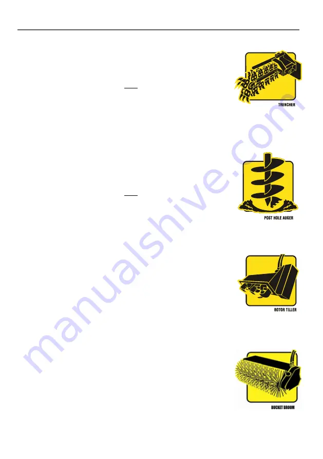
POST HOLE AUGER & TREE PLANTER AUGER SAFETY RULES

Always…

•  Establish and maintain a minimum 4 meter (12 foot) exclusion zone 

around the local working area and ensure no person other than the 
operator, enters this zone whilst the machine’s engine is running.

•  Check with Local Authorities and land owners about the presence 

of underground services within the prospective working area prior 
to commencement of work. (Dial 

1100

 to establish any existing 

underground services before work commences). 

•  Ensure excavations are located a minimum of 2 meters away from 

any underground service.

Never…

•  Place any article or body part under the auger at any time


ROTARY HOE (TILLER) SAFETY RULES

Always…

•  Establish and maintain a minimum 4 meter (12 foot) exclusion zone 

around the local working area and ensure no person other than the 
operator, enters this zone whilst the machine’s engine is running.

Never…

•  Place any article or body part near or under the Rotary Hoe at    

any time.

•  Carry out maintenance of any type whilst the Rotary Hoe is attached 

to the Loader or any other power source.


BUCKET BROOM SAFETY RULES

Always…

•  Establish and maintain a minimum 4 meter (12 foot) exclusion zone 

around the local working area and ensure no person other than the 
operator, enters this zone whilst the machine’s engine is running.

•  Keep the general working area clear of bystanders and other 

workers. Loader operations typically rely on rapid movement and 
direction changes. It is important, therefore, that the whole operation 
area is kept clear of other personnel and operators maintain 
vigilance about their immediate surroundings.

•  Wear respiratory and eye protection whilst using the Bucket Broom.

Never…

•  Place any body part under the bucket broom at any time

.

TRENCHER SAFETY RULES

Always…

•  Establish and maintain a minimum 4 meter (12 foot) exclusion zone 

around the local working area a nd ensure no person other than the 
operator, enters this zone whilst the machine’s engine is running.

•  Check with Local Authorities and land owners about the presence 

of underground services within the prospective working area prior 
to commencement of work. (Dial 

1100

 to establish any existing 

underground services before work commences.)

•  Ensure trenches are located a minimum of 2 meters away from any 

underground service.

Never…

•  Place any article or body part under the trencher at any time


Summary of Contents for 8D Series

Page 1: ...8D SERIES OPERATOR S MANUAL WWW KANGALOADER COM 1300 4 KANGA PM 000130 ...

Page 2: ......

Page 3: ...date SWL terms to ROC LC 8 Feb 2020 14 68 Update ROC add Tipping Load LC REVISION SHEET Loader identification Below is a quick reference for identifying your Kanga loader The first letter represents the engine type D for Diesel and P for Petrol The second represents the drive type W for Wheel and T for Track The Next letter represents the model of Loader with the first number in the Numerical sequ...

Page 4: ...rchaser must fill out and return the warranty registration card within 30 days of purchase in order to validate the warranty Repairs Warranty repairs must be carried out by an authorised Kanga Dealer For details contact Kanga Loaders on 1300 4 KANGA 1300 4 52642 Battery Warranty Pro rata One to three months Free replacement Four to twelve months Pro rata over 12 months Exclusions No Warranty Norma...

Page 5: ... hydraulic and engine oil levels are maintained and that maintenance is carried out as required in the manuals Claims for damage as a result of insufficient oil levels will not be recognised Kanga Loaders may from time to time change the design of its products Nothing contained in this warranty shall be construed as obligating Kanga Loaders to incorporate such changes into previously manufactured ...

Page 6: ...n this publication show details or attachments that may be different from your machine Guards and covers may have been removed for illustrative purposes however the machine in its operational state must always be operated with all guards and safety controls in place Continuing improvement and advancement of product design may have caused changes to your machine which are not included in this publi...

Page 7: ...ATION 11 SAFE OPERATION 12 FIVE STEPS TO EFFECTIVE JSEA 15 NO GO ZONES FOR UNDERGROUND UTILITY SERVICES 15 OPERATOR SAFETY summary 17 TASK PLANNING FOR THE KANGA LOADER 18 PRE OPERATIONAL RISK ASSESSMENT 20 RISK ASSESSMENT 23 OPERATING INSTRUCTIONS OPERATING INSTRUCTIONS 24 ATTACHMENTS HYDRAULIC ATTACHMENT CONNECTIONS 29 4 IN 1 OPERATING INSTRUCTIONS 30 POWER HEAD OPERATING INSTRUCTIONS 31 TRENCHE...

Page 8: ...ine 49 SERVICE TASKS Hydraulics 50 SERVICE TASK Trenching Valve 52 SERVICE TASKS Visual 54 SERVICE TASKS Grease Nipple 54 SERVICE TASK Radiator Diesel 54 SERVICE TASKS Battery 54 SERVICE TASKS Pivot Pins 54 SERVICE TASKS Tyre Pressure 56 TRACKS 8 Series 57 DECALS 64 SERVICE CHART 65 MAINTENANCE SCHEDULE 66 SPECIFICATION SPECIFICATIONS 8 series 68 DIMENSIONS 8 series 69 TROUBLE SHOOTING TROUBLESHOO...

Page 9: ...QLD SERVICE QLD SERVICE Phone Aus 07 3441 9222 Int 61 7 3441 9200 Address 4 Octal Street Yatala QLD 4207 VIC SERVICE VIC SERVICE Phone Aus 03 8793 6600 Int 61 3 8793 6600 Address 85 Cheltenham Road Dandenong VIC 3175 NSW SERVICE NSW SERVICE Phone Aus 02 9854 1444 Int 61 2 9854 1444 Address 19 McKay Close Wetherill Park NSW 2164 SOUTHERN NSW ACT SOUTHERN NSW ACT Phone Aus 02 6297 9099 Int 61 2 6297...

Page 10: ...y are attached securely 3 Inspect all areas for evidence of hydraulic oil engine oil or fuel leakage 4 Inspect Arm assembly area for firm attachment and sufficient lubrication Check hydraulic cylinders for oil leakage and visible damage 5 Check hydraulic oil lines for correct connection and for signs of leakage 6 Check wheel and tyre assemblies for loose or missing wheel nuts any visible damage an...

Page 11: ...understand the process for use of the JSEA chart stop the job and consult a qualified Occupational Health and Safety consultant THESE SYMBOLS ARE PICTOGRAMS AND REFER TO COMPULSORY PERSONAL PROTECTIVE EQUIPMENT PPE THAT MUST BE WORN AND OR ACTIONS THAT MUST BE TAKEN BY THE OPERATOR TO ALLOW SAFE OPERATION OF THE MACHINE TO OCCUR THIS SYMBOL HAS BEEN USED THROUGHOUT THIS MANUAL TO HIGHLIGHT IMPORTA...

Page 12: ...cessary When lifting the machine use appropriately rated slings and shackles and attach securely to the lifting point on the top of the machine Always use the tie down points on each side of the machine to secure the Loader when transporting Always use witches hats signage and traffic signals to control the unloading loading zone particularly when in close proximity to operational roads Before Com...

Page 13: ...ilure to do so can affect the stability of the Loader and may also damage the drive of your machine Come to a complete stop before operating other hydraulic controls Reverse down slopes at slow speed when carrying loads Ensure the machine is fully stopped and turned off before alighting or exiting the machine Never use control levers as hand holds instead utilize the handholds using the thumbs and...

Page 14: ...h exhaust engine parts hydraulic pipes and fittings drive chains friction parts or guards Park or leave Loader unattended on a slope Remove safety decals Remove safety guarding During operation use mobile telephones or portable radios Operate machine for extended periods at full throttle Always exercise care when operating on slopes The Kanga Loader has been designed to be able to access restricte...

Page 15: ...ivity changes or when there is a change of personnel or after an appropriate length of time NO GO ZONES FOR UNDERGROUND UTILITY SERVICES No work is to commence on any worksite until you have checked if it contains underground services Here is how you can find out The Dial Before You Dig service in Australia dial 1100 provides free and easy access to the records of a large number of organizations i...

Page 16: ...k near overhead powerlines or any electrical conductors Do not drive with Kanga loader on the back of a truck or trailer with hydraulic arms elevated or with attachments connected as they could enter the exclusion zone 3 meters Avoid driving or working in or around exclusion zone for overhead and underground powerlines Exclusion zone for unauthorised persons is 3 meters up to 132 kV and is 6 meter...

Page 17: ... SAFETY SUMMARY FAILURE TO READ THESE SAFETY RULES PRIOR TO ANY MACHINE OPERATIONS MAY LEAD TO SERIOUS INJURY PROPERTY DAMAGE OR DEATH DANGER 15 OPTIMUM OPERATION OF THIS MACHINE IS ACHIEVED AT 2 3 TO 3 4 THROTTLE ...

Page 18: ...ction manual Perform a pre operational inspection of the Loader to identify any faults Ensure all safety features are operable Use bunting flags or witches hats to demarcate or isolate work area Wear additional PPE such as safety glasses hearing protection and hard hat and steel capped boots Task execution Discuss work plans with other workers persons in the area Coordinate Loader activities with ...

Page 19: ...Identify what else could go wrong Decide on control measures to prevent things going wrong Make sure the hazards are controlled before starting work Think about the consequences to your quality of life your income your family your children and everything you value Are these things worth the risk of rushing or cutting corners It s not just your life that could be affected you may shatter the lives ...

Page 20: ...s Foreman and contact number Prepared By Name 1 Signature Position Name 2 Signature Position Received and reviewed by Name Signature Position Date Date work method prepared must be within last 12 months Date work to be commenced Actions before work commences e g signage bunting demarcation isolation Action during work Actions after work is complete ...

Page 21: ...ot work etc Training and instruction Warning signs and control measures Plant equipment materials to be used and the maintenance checks to be completed details at back of SWMS also Loader Personal protective equipment requirements Legislation codes of practice standards applicable List of attachments e g material safety data sheets diagrams etc ...

Page 22: ...um financial cost for repairs reinstatement 3 Possible May occur at some time 10 15 Plan and implement risk control measures after performing a Step Back 5 X 5 risk assessment Seek advice from the manufacturer if any doubt exists 2 Minor First Aid treatment minor risk damage to plant and equipment minor financial cost for repairs reinstatement 2 Unlikely Could occur at some time 6 9 No immediate r...

Page 23: ... POTENTIAL HAZARDS What may cause an injury illness to occur RAW RISK RANKING L C R HAZARD CONTROLS What controls will be put in place to prevent an injury illness N B Control measures must not raise or create an increased risk RESIDUAL RISK RANKING L C R WHO WILL MONITOR ENSURE THAT THIS IS DONE ...

Page 24: ...ess standing with both feet on the driving platform and holding the grip handles ensuring non operating personnel are clear of the Loader CAUTION First time users to use slow 1 3 throttle to practice safe operation before commencing work The recommended normal operating speed of the machine is 2 3 to Throttle CAUTION The kanga Loader is not fitted with a seat belt The standing position is a safety...

Page 25: ... be achieved by varying the amount and or direction of power supplied to each side of the machine The machine is capable of turning in its own length by applying equal forward and reverse power to opposite sides of the machine While moving forward a gentle turn to the left for instance can be made by slightly increasing the power to the right hand side or by reducing the power to the left hand sid...

Page 26: ...t drive reverse Used to manuever the loader can be used alone or in conjunction with left hand drive 6 Attachment tilt control forward Attachment tilt control backward Used to keep load level or to dump bucket of dirt 7 Throttle increase rpm up Throttle decrease rpm down For trenching set throttle at maximum to maximize hydrualic horsepower 8 2 speed drive control slow up 2 speed drive control fas...

Page 27: ...n surface Do not unload a trailer on a slope Ensure bystanders are sufficiently clear All loading unloading to be carried out using a ramp must be done at a slow speed with due care for personal safety and damage to equipment Practice the manoeuvres first on flat ground if necessary Use appropriately rated slings and shackles and attach to the lifting point on the top of the machine when lifting t...

Page 28: ...NE No other attachment is to be used on this machine unless the design and use of the attachment has been assessed and authorised by Kanga and has been supported by a compliant Risk Assessment which has been verified and validated by the Risk Management Consultants ATTACHMENTS ...

Page 29: ... Female Cover HC 000033 Yellow Black Red Blue White Purple Green COLOUR CODING OF QRC s FOR ATTACHMENTS Right Side Controlled by the Auxiliary lever on the Control Panel B MALE QRC For Power Head Under Road Borer Cement Mixer Wood Chipper Log Splitter Rotating Log Grab Rock Breaker A FEMALE QRC For Power Head Trenchers Under Road Borer Backhoe Rotary hoe Vibrating Plough Cement Mixer Wood Chipper ...

Page 30: ...aterial in the bucket on slopes or rough ground always keep the bucket close to ground level This lowers the centre of gravity of the Loader and maximises stability The material may then be dumped into a trailer or utility truck for removal or repositioning on the site When scraping levelling and surface stripping lower the bucket to the ground tilt it down and so raise the front wheels slightly o...

Page 31: ... that they are in good condition and firmly attached Start the auger turning in a clockwise direction by activating the AUX lever downwards Lower the auger by pushing the ARM lever forward If the ground is hard the front wheels of the Kanga Loader will lift off the ground As the auger cuts into the ground the arc of the arm travel will move it out of vertical To keep the auger vertical move the Ka...

Page 32: ...ety chapter in this manual CAUTION Prior to commencing any digging operations check with the Local Authorities and the land owner that there are no buried services Power phone water gas sewage etc in the vicinity Australia ONLY Phone 1100 DIAL BEFORE YOU DIG Read the Safety instructions in this Manual Keep clear of the Trencher at all times 4m minimum FITTING A TRENCHER PRE OPERATION CHECK OPERATI...

Page 33: ...m that the backhoe is securely attached to the loader and the couplings are engaged Check all joints for leaks Tighten and repair as required Check that the backhoe bucket teeth hydraulic hoses and cylinders are in good condition 2 Place the backhoe wheels in the locked position Place the AUX lever in neutral Start the engine then adjust the engine RPM lever to suit the operation and hydraulic req...

Page 34: ...om should only be pushed with the loader drive system CAUTION Prior to commencing work read the Safety Rules of this Kanga Loader Manual FITTING THE BUCKET BROOM OPERATING INSTRUCTIONS SET TRENCHING VALVE FOR BUCKET BROOM USE The trenching valve is located on the left hand side of the loader This is a load sensing valve and can be set to automatically regulate the speed of travel when using a broo...

Page 35: ...in rotating NOTE The rotary hoe should only be pulled with the loader drive system Do not push the rotary hoe OPERATING INSTRUCTIONS CAUTION Establish and maintain a minimum 4m exclusion zone around the working area No person other than the operator should enter the work zone while the machine s engine is running Observe all underground utility markings carefully Maintain a no work zone six feet f...

Page 36: ... the software design text and graphics comprised in kangaloader com and the selection and layout of kangaloader com are owned or licensed by us and protected by copyright under the laws of Australia and other countries 1 2 You may view this document and our website and save an electronic copy of the website solely for the usual operation of your web browser visiting the site 1 3 You must not other...

Page 37: ...nd the local working area and ensure no person other than the operator enters this zone whilst the machine s engine is running Keep the general working area clear of bystanders and other workers Loader operations typically rely on rapid movement and direction changes It is important therefore that the whole operational area is kept clear of other personnel and operators maintain vigilance about th...

Page 38: ...NT SERIAL NUMBERS KANGA Serial No Engine Type Serial No 2 Speed Valves Wheel Motors FRONT RIGHT REAR RIGHT FRONT LEFT REAR LEFT Lift Ram Tilt Ram Hydraulic Pump Control Valve Date Purchased SERIAL NUMBER REGISTRATION ...

Page 39: ...oader and attachments and have been provided a copy of these procedures for reference and use 3 Have received a copy and understand the Operators Manual and safety information contained therein for all equipment and attachments supplied 4 Understand that I am required to perform a risk assessment JSEA covering all tasks before I operate this machine and or any attachment 5 Understand the warranty ...

Page 40: ...hase on the Registration Form Owner Phone Address Mobile Town City Fax Country Post Code Delivery Date KANGA SERIAL NO Email Kanga Agent Sales Person I The Purchaser have read and fully understand the Operator s Manual Safety Instructions and warranty conditions Warranty will only be accepted if this Certificate is completed and returned to AUSTRALIA KANGA LOADERS GLOBAL 4 OCTAL ST YATALA QLD 4207...

Page 41: ...ctly 5 Unusual noises or vibrations 6 Petrol Diesel engine Idle 1350 1450 900 1000rpm 7 Petrol Diesel engine max 3550 3650 3800 3850rpm 8 Is Loader easy to start 9 Is Hour Meter working Test time hrs 10 Check that lift cylinder stops in correct position 11 Aux stop cable check cable length is correct test operation 5 times GUIDANCE 1 Correct stickers applied UK C E sticker 2 Correct Tyre Pressure ...

Page 42: ...CKET BROOM SAFETY RULES Always Establish and maintain a minimum 4 meter 12 foot exclusion zone around the local working area and ensure no person other than the operator enters this zone whilst the machine s engine is running Keep the general working area clear of bystanders and other workers Loader operations typically rely on rapid movement and direction changes It is important therefore that th...

Page 43: ... commences Install effective perimeter hoarding barricades 6ft high around the exclusion zone Wear respiratory and eye protection Never Place any article or body part under or in close proximity to the Stump Grinder at any time Touch the exhaust engine parts hydraulic pipes and fittings guards or Stump Grinder Wheel soon after use Always Establish and maintain a minimum 4 meter 12 foot exclusion z...

Page 44: ...s by KANGA Loader operators For expert advice and quality service consult an expert repairer we recommend an authorised kanga repairer The owner should retain evidence that proper maintenance has been performed as prescribed A claim against a warranty will not qualify if it results from lack of maintenance and not from defective material or authorised workmanship CAUTION DO NOT operate a Kanga Loa...

Page 45: ...attery Free of corrosion Good condition check indicator Safety Decals Legible All in place Engine Adequate crankcase oil level Check Air cleaner Filter No Leakage Fuel Adquate Fuel Level Drain water tap if fitted Optional Extra Water Diesel Loader Radiator Hoses water level Operating Manual Present with machine ATTACHMENT Guarding Good condition Secure Good condition of hoses Check for leaks Hydra...

Page 46: ...pt clean and free of oil grease and debris Designate the effective maintenance work area using witches hats Never Rely solely on the machine hydraulics to keep the Arm elevated whilst carrying out maintenance Locking Pins should always be used to physically hold the boom in the raised position Raise or lower the boom with the Locking Pins in place Arm Safety Pin Replacement DL 000782 Rubber Safety...

Page 47: ...a Charge Warning Light and an Oil Warning Light A Water Temperature Warning Light and Glow Plug Light are also included on the Instrument Panel for the diesel Loaders only KUBOTA REPLACEMENT KEY SWITCH ASSEMBLY Part DL 000512 KUBOTA REPLACEMENT KEY Part KS 000092 per set HOUR CLOCK Part DL 000817 LIGHT RED DASH LIGHT 8 SERIES Part EC 100155 LIGHT BLUE DASH LIGHT 8 SERIES Part EC 100158 LIGHT GREEN...

Page 48: ...LADE MICRO 25 AMP CLEAR Part Number EC 100131 FUSE BLADE MICRO 30 AMP GREEN Part Number EC 100132 DIODE BLOCKING 6 AMP Part Number EC 100133 FUSE 50 AMP SPADE Part Number EC 100035 GLOW TIMER Part Number EC 000286 STOP TIMER Part Number EC 100176 BATTERY12V Fuse 50 AMP Rear cooling fan 35 amp N O 30Amp 6 amp Run Diode Glow Plug 25Amp Rear cooling fan 2 Speed 20Amp N O Accessory power 35 amp 15Amp ...

Page 49: ... system contains a pre mix of water and coolant to a 50 50 ratio Water capacity is 3 1 litres The radiator cap should be periodically checked for proper performance and replaced as required FAN BELT DIESEL ENGINE Part Number KS 000327 The Fan Belt should be checked regularly for signs of wear and changed in accordance with the Manufacturers recommendation see engine manual FUEL FILTER FOR DIESEL F...

Page 50: ...in fluid levels will indicate leakage Inspect all hydraulic hoses tubes fittings valves and rams for leaks and damage Tighten loose fittings and replace damaged components Check all three pressure settings see procedure on opposite page Adjust if necessary HYDRAULIC FILTERS Replace the return line filter after every 200 operating hours Service the pressure filter after every 500 operating hours Pr...

Page 51: ...l Models NOTE If adjustment is necessary slacken off the lock nut on the main pressure relief valve and wind in the screw to increase the pressure or back off the screw to reduce the pressure Retighten the lock nut when adjustments are complete LIFT PRESSURE Connect an accurate pressure gauge with a range 0 300 bar 0 4 300 PSI to the Tp1 Test Point Check the pressure while pulling the arm control ...

Page 52: ...mpensator 2 to the A port and to the trencher motor NOTE If the flow control valve 1 is fully closed all flow is directed to the trencher motor and no oil can flow to the drive motors no regulating occurs Return oil from the trencher motor flows through the C port and the over centre valve 3 to the Tank T port In the event of excessively hard trenching with the drive motor driving against the tren...

Page 53: ...cher chain running forward The pressure should be set at 69 76 bar 1000 1100 PSI on all models Sequence Valve 4 Setting Flow Control Valve 1 fully closed turned clockwise Aux Lever on main control valve up trencher chain running backwards The pressure should be set at 203 bar 2950 PSI on B Series Diesel Models Checking Trenching Valve Function With trencher above ground and chain running forward A...

Page 54: ...ASKS BATTERY BATTERY Part Number DL 000605 The battery provided with the Loader is maintenance free An indicator at the top of the battery displays its condition according to a displayed colour Ensure that the terminals are tight and that covers and battery leads are not damaged SERVICE TASKS RADIATOR DIESEL RADIATOR Radiator Hoses and connections should be checked on a regular basis for cracks an...

Page 55: ...ot pins and bushes for wear and damage at an interval of 200 operating hours 0K10901 0K10901 0K10902 0K10903 ATTACHMENT PLATE REPLACEABLE PARTS NO DESCRIPTION PART NO 1 Attachment Plate Assembly DL 000430 2 Tilt Arm Pins Kit Pin F 39 0K10902 3 AttachmentPlate Pin E 96mm 0K10901 4 Tilt Cylinder Pin Pin G 65mm 0K10903 5 Tilt Arm Trunion Mount Kanga 8 Series Pair DL 000537 YE ...

Page 56: ...6 UNF Part Number FA 000530 RIM TRACK BLACK 10X3 Part Number DL 000469 BL CHN ROLLER FOR S8 172 PITCHES Part Number DL 003250 TYRE INNER TRACK DRIVE KENDA 3204KS Part Number DL 002913 Visually check tyres on a daily basis and check tyre pressure every 50 operating hours and check for wear and damage to tyres and tracks 8 SERIES TYRE PRESSURES Tyre Size Recommended Pressure Gross weight Kgs KPA PSI...

Page 57: ...ing a steep bank and with little load in the bucket Do not use this machine on slopes without assessing the risks and fully identifying the required risk control measures by use of a Job Safety and Environment Analysis JSEA or Risk Assessment RA Do NOT operate on slopes without undertaking a risk assessment and complying with the requirements outlined in the Safe Operation section of the manual NO...

Page 58: ... rear of the Loader 4 Place the bucket flat on the ground 5 Tilt the bucket forward as if dumping and the Loader will lift clear of the ground supported by the block and the bucket 6 When tracks are clear of ground at both ends place another wooden block or a stand under the base at the front of the Loader 7 Deflate tyres to 25psi 8 Remove the wheel nuts and use a suitable lever to remove the fron...

Page 59: ...e wrench to rotate the rear hub so the studs will line up with the wheel while depressing forward reverse control lever Do not start the engine 9 Locate the rear wheel on the hub and studs and install one wheel nut to hold the wheel to the hub 10 Rotate the front hub with an adjustable wrench to line up the studs to the wheel while depressing forward reverse control lever Do not start engine To do...

Page 60: ... set up with option 1 However if customers would like to change the tracks around to try a different set up they can We feel that the way that they are supplied is the best all round set up Option 2 is best suited for muddy or sandy conditions URO Track Roller Train 8 Series 1 Per Side Part Number DL 003254 OPTION 2 OPTION 1 FACTORY SET SINGLE DIRECTION ...

Page 61: ...DL 003251 2 Once you have found the joining link place 2 x 6mm bolts or suitable pins to hold the chain while you remove the joiner link 3 Pull the locking bolts out and remove the chain simply by pulling it through the track segments Then turn the track onto it s other side and repeat steps 1 2 and 3 4 Lay segments out on the floor in the required pattern and then feed the chain in from one end t...

Page 62: ...rough and secured with pins lay the track it on it s side Place the securing pins through the link in such a manner so as to expose the holes through which you will fit the joining link 7 With the track on its side install the joining link from the inside to the outside so that the spring clip is on the outside Flip the track over and repeat to the other side remove the locking pins bolts and the ...

Page 63: ...en pry the R H segment back as far as you can with a screwdriver to expose 2 full side plates 4 x pins 4 Use chain splitter or angle grinder to grind off 2 pins that are on the outside of the 4 pins Grind off these 2 pins to remove 1 x link Use a pin punch to drive the pins out to release the chain section 5 Turn the track over and perform the same on the other side to release the track so it is n...

Page 64: ...00212 1 17 DECAL LOADER 8 SERIES LIFTING LUG DE 000225 2 18 DECAL LOADER NAME PLATE AUXILLARY DE 000236 1 19 DECAL LOADER NAME PLATE HYDRAULIC OIL DE 000237 1 20 DECAL LOADER ARM SAFETY PIN DE 000238 3 21 DECAL KANGA SERVICE AND SPARES DE 000731 1 22 DECAL KANGA FUEL TANK DIESEL FUEL LEVEL DE 000732 2 23 DECAL FILL BOTH FUEL TANKS DE 000777 2 24 DECAL LEFT HAND DRIVE LIFT NAMEPLATE DE 000800 1 25 ...

Page 65: ... I R I I I I R TYRE PRESSURES I I I I I I I I I I I I I I I I DAILY ITEMS TO BE CHECKED ON A DAILY BASIS HOURS 8 8 8 8 8 8 8 8 8 8 8 8 8 8 8 8 PRE CLEANER FOAM BOWL C C C C C C C C C C C C C C C C VISUAL CHECK CRACKS WEAR I I I I I I I I I I I I I I I I RADIATOR WATER LEVEL DIESEL I I I I I I I I I I I I I I I I GREASE NIPPLES PINS L L L L L L L L L L L L L L L L R Replace C Clean as required L Lu...

Page 66: ...E INTERMEDIATE SERVICE MINOR SERVICE MAJOR SERVICE MODEL 600Hr 700Hr 800Hr 900Hr 1000Hr 8D Series DATE DATE DATE DATE DATE S E R V I C E S T A M P S E R V I C E S T A M P S E R V I C E S T A M P S E R V I C E S T A M P S E R V I C E S T A M P S E R V I C E S T A M P S E R V I C E S T A M P S E R V I C E S T A M P S E R V I C E S T A M P S E R V I C E S T A M P MAINTENANCE SCHEDULE 8B SERIES ...

Page 67: ... C E S T A M P S E R V I C E S T A M P S E R V I C E S T A M P S E R V I C E S T A M P S E R V I C E S T A M P S E R V I C E S T A M P S E R V I C E S T A M P MAINTENANCE SCHEDULE 8B SERIES Continued NOTE The warranty on the equipment is subject to the periodic maintenance being carried out at the intervals specified If a service provider other than Kanga Loaders is used maintenance records from t...

Page 68: ... V1505 Diesel SAE Gross Power intermittent 26 5 kW 35 5 hp Torque 73Nm 53 8 lbs ft DRIVE SYSTEM Drive Control Soft Touch Hand Levers Throttle Control Hand Levers Tracks Wheels Tracks Direct Drive Hydraulic Motors All Wheel Drive System Yes Optional 2 Speed Wheel Diameter 10 x 5 Track Over Wheel HYDRAULICS Nominal Pump Output 3000rpm 50 L min 13 2 US gal min System Pressure 220 bar 3200 psi Hyd Res...

Page 69: ...69 DIMENSIONS 8 SERIES ...

Page 70: ... to proper setting Contact service Agent Excessive oil leak past lift cylinder piston seal Repair or replace cylinder as necessary Arm will not lower Hydraulic oil system low Check oil and replenish as necessary Oil level should not change Leaks may be present Damaged or blocked hydraulic line Remove line and remove any obstructions or replace line as necessary Malfunctioning pump Replace Hydrauli...

Page 71: ...t or coupling Repair or replace as necessary Worn or chipped pump gears Replace pump gears as necessary Control rod or lever broken or disconnected Repair or replace control rod or lever Hydraulic lines incorrectly connected at Control Valve Correctly connect line at Control Valve Arm rises and lowers erratically Lift Control Valve relief set too low allowing oil to return to reservoir Adjust reli...

Page 72: ...uld not change Leaks may be present Damaged or blocked line Remove line and remove any obstructions or replace line as necessary Binding drive motor s Repair or replace motor s as necessary Relief valve setting Adjust relief valve DRIVE SYSTEM TROUBLE PROBABLE CAUSE REMEDY Engine will not crank over Low battery output Recharge or replace battery Loose disconnected or broken battery cables Inspect ...

Page 73: ...as necessary Malfunctioning pump Replace Hydraulic Pump as necessary Worn Control Valve spool Check pressure delivery from Control Valve Repair or replace valve as required Attachment plate pivot pin seized or otherwise damaged Replace pivot pin andbushing as necessary Grease thoroughly Excessive oil leak past cylinder piston seal or motor rotating group Repair or replace cylinder motor as necessa...

Page 74: ......

Page 75: ......

Page 76: ...ORIA VICTORIA Phone Aus 03 8793 6600 Int 61 3 8793 6600 Address 85 Cheltenham Road Dandenong VIC 3175 NEW SOUTH WALES NEW SOUTH WALES Phone Aus 02 9854 1444 Int 61 2 9854 1444 Address 19 McKay Close Wetherill Park NSW 2164 SOUTHERN NSW ACT SOUTHERN NSW ACT Phone Aus 02 6297 9099 Int 61 2 6297 9099 Address 1 49 Yass Road Queanbeyan NSW 2620 ...

Reviews: