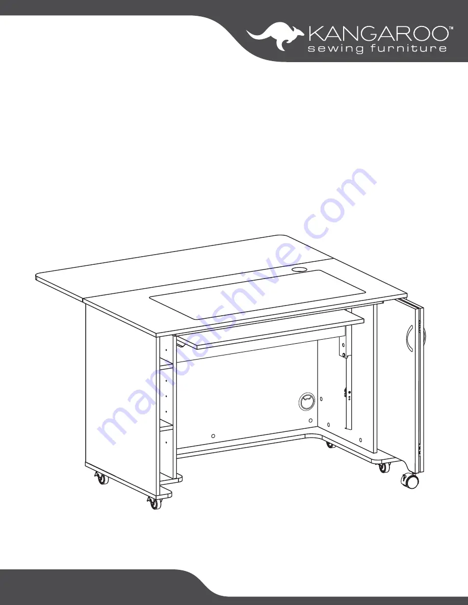
background image

SEW IN COMFORT. SEW LONGER.™

A SSEMBLY  INSTRUC TIONS

M o d   X L

ITEM NO.:

2071 Hydraulic Lift
2061 Electric Lift

Summary of Contents for 2061

Page 1: ...SEW IN COMFORT SEW LONGER ASSEMBLY INSTRUCTIONS Mod XL ITEM NO 2071 Hydraulic Lift 2061 Electric Lift ...

Page 2: ...lled cam bolt holes to help the cam bolts screw in better 4 Glue provided is to secure wood dowels in place and is optional If glue is used during assembly locate the appropriate hole for the dowel place a small amount of glue in the hole and insert the dowel Wipe away excess glue immediately It is not necessary to glue the other end of the dowel when attaching to other parts Use and Care Your cab...

Page 3: ...Left Inside Panel 1 1 of 3 X Left Side Panel 1 1 of 3 Z Right Side Panel 1 1 of 3 A Top Panel 1 2 of 3 A2 Lift Platform 1 2 of 3 ITEM DESCRIPTION QTY PACK A1 Cover Panel 1 2 of 3 G Bottom 1 2 of 3 E Shelves 2 2 of 3 D Back Panel 1 2 of 3 A3 Quilt Leaf Panel 1 3 of 3 O1 Left Gateleg Panel 1 3 of 3 O2 Right Gateleg Panel 1 3 of 3 Y1 Y2 X Z A3 A A1 D E E G V1 V2 A2 O1 O2 ...

Page 4: ... 3 5x14 Screw x80 s1 Handle x2 h 4x20 Fix Bolt x4 b2 Magnet x1 Catch Plate x1 m Magnet x2 Catch Plate x2 m1 Butt Hinge x9 h1 Alignment Pin x2 s3 5x30 Screw x5 s2 Hinge Body x2 g1 Peg x8 p1 Lift x1 Lift Rail Left x1 Lift Rail Right x1 TIP Keep all the parts in their individually labeled bags This will make finding parts easier as you assemble your cabinet 14mm Wrench x1 r3 Allen Wrench x1 a Metal S...

Page 5: ...ase contact our Customer Service Team at 1 800 533 7347 ext 1 during normal business hours with any assembly related questions Locking Plate Caster x4 t2 8x16 Fix Bolt x16 b1 Attach t2 Locking Plate Cast ers to the underside of Panel G using b1 Fix Bolts Tighten with Allen Wrench Flip Panel G over Attach c1 Cam Bolts to Panel G Set Panel G aside 6x35 Cam Bolt x9 c1 G G Allen Wrench x1 a ...

Page 6: ...binet 6x35 Cam Bolt x4 c1 8x30 Dowel Pin x8 d1 Attach 2 c1 Cam Bolts to Panel X as shown Insert 4 d1 Dowel Pins into the edges of Panel X as shown Attach 2 c1 Cam Bolts to Panel Z as shown Insert 4 d1 Dowel Pins into the edges of Panel Z as shown X Z ...

Page 7: ...nel Y1 as shown TIP Spray a small amount of WD 40 or similar lubricant onto a paper towel and wipe the newly installed rails This will make lift installation and operation easier D Y1 6x35 Cam Bolt x4 c1 8x30 Dowel Pin x14 d1 Lift Rail Left x1 3 5x14 Screw x3 s1 Attach c1 Cam Bolts to Panel D as shown Insert d1 Dowel Pins into the edges of Panel D as shown ...

Page 8: ...pe the newly installed rails This will make lift installation and operation easier Y2 D X Z Lift Rail Right x1 3 5x14 Screw x3 s1 5 8 Cam Cover x4 c2 NOTE The above illustration shows upside down assembly of the cabinet This is necessary to attach the bottom Attach Panels X and Z to Panel D as shown inserting cam bolts into cam locks Tighten cam locks and apply c2 Cam Covers 8x30 Dowel Pin x4 d1 ...

Page 9: ...sembly Instructions 2061 2071 9 Part 1 Main Cabinet Y1 Y2 Z D X 5 8 Cam Cover x4 c2 Attach Panels Y1 and Y2 to Panel D as shown inserting cam bolts into cam locks Tighten cam locks and apply c2 Cam Covers ...

Page 10: ...x2 s20 Lower Panel G onto Panels Z Y2 D Y1 and X as shown inserting cam bolts into cam locks Tighten cam locks and apply c2 Cam Covers Attach Panel G to Panel Z using s20 Screws as shown Make sure casters are locked and flip cabinet over onto its casters You may need a friend to help you but it is not requred ...

Page 11: ...ock falls out before complete assembly Call Customer Service at 1 800 533 7347 ext 1 for assistance or visit www arrowsewing com assembly and find the Alternate Airlift Attachment Steps video This illustration shows the back view of the Lift Notice the wooden block and zip tie the wooden block holds the piston in place so that the cables can be easily handled and inserted into the Lift Rails insta...

Page 12: ...ble is hooked into the rail tabs on both sides Cut the zip tie on the wooden block but DO NOT remove the block yet Lower the Lift to first lock position and remove the wooden block DO NOT ADJUST LIFT POSITION until the top is installed or you risk the Lift coming out and cables becoming disengaged Plastic guides Lift rail Cable Lift rail Rail tabs ...

Page 13: ... Cam Bolt x10 c1 Metal Support Bar x1 5x30 Screw x5 s2 Magnet x1 m 3 5x14 Screw x2 s1 Attach c1 Cam Bolts to Panel A as shown Attach m Magnet to Panel A with s1 Screws as shown Set aside magnet plate for later use Attach the Metal Support Bar to Panel A with s2 Screws as shown ...

Page 14: ...cam bolts into cam locks Tighten cam locks and cover with c2 Cam Covers Note the small hole in the back right corner See inset illustration you will need a long screwdriver to reach through the hole and tighten the cam lock Insert p1 Pegs into pre drilled Panels X and Y1 taking care to be sure the pegs are evenly spaced Slide Panel E shelves into place as shown Z D Y2 ...

Page 15: ... 6x6 Screw x4 s7 Catch Plate x1 m Attach t1 Caster to Panel V1 as shown Tighten with r3 Wrench Attach g1 Hinge Body to Panel V2 as shown using s1 Screws Attach h1 Butt Hinges connecting Panels V1 and V2 as shown using s1 Screws Attach m Magnet Catch Plate using s1 Screws s1 h1 Attach g1 Hinge Body on Panel V2 to pre installed door slider on Panel Z using s7 Screws g1 ...

Page 16: ...on of your hinge Adjust hinge horizontally Loosen the screw indicated and slide the hinge body left or right to adjust horizontal position of your hinge Adjust door depth Loosen the screws indicated and slide the hinge body in or out to adjust depth of your door For more information on adjusting your hinges please visit us at www arrowsewing com and find our Product Support Videos ...

Page 17: ...Assembly Instructions 2061 2071 17 Part 4 Door V2 V1 h b2 Handle x2 h 4x20 Fix Bolt x4 b2 Attach h Handles using b2 Fix Bolts ...

Page 18: ...ted using s1 Screws Set magnets aside for later m1 s1 s3 h1 s1 t1 Attach h1 Butt Hinges to Panels O1 and O2 as illus trated using s1 Screws Screw s3 Alignment Pins into the top edges of Panels O1 and O2 as illustrated Attach t1 Casters to Panels O1 and O2 as illustrated Tighten with Wrench Attach Panels O1 and O2 to Panel D as il lustrated using s1 Screws to attach h1 Butt Hinges s1 h1 h1 s1 s1 h1...

Page 19: ...Magnet x2 m1 Butt Hinge x3 h1 3 5x14 Screw x22 s1 Attach m1 Magnets to Panel A3 as illustrated using s1 Screws Attach h1 Butt Hinges to Panel A3 as illustrated using s1 Screws Balancing Panel A3 on Panels O1 and O2 attach Panel A3 to Panel A with h1 Hinges using s1 Screws s1 h1 s1 h1 ...

Page 20: ...Assembly Instructions 2061 2071 20 Completed Mod XL Sewing Cabinet ...

Page 21: ... intended use any condition resulting from incorrect or inadequate maintenance cleaning care or neglect cuts or scratches caster damage as a result of moving furniture fully loaded or with locked casters damage resulting from electrical surge or lightning or use in commecial or education environments Arrow Sewing Furniture is designed for residential use only ARROW SHALL HAVE NO LIABILITY for ANY ...

Page 22: ...rists straighter stitches and an elevated sewing experience Arrow s 1 Rated Height Adjustable Sewing Chair is a must have accessory for your dream sewing room Cute comfortable and convenient our lovable sewing chairs feature vibrant sewing themed patterns 360 swivel access and lumbar support for long hours at your workstation Don t look now but under every seat cushion is a hidden storage compartm...

Reviews: