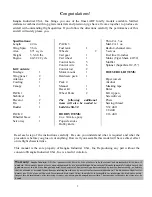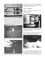
Make a “Z” bend in the control wire and install
the servo arm. Adjust as necessary for proper
operation.
A slight bend in the control wire may be
necessary for smooth operation.
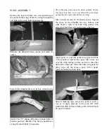
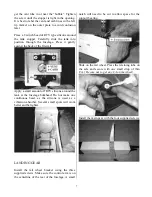
Locate the two control rods. The one for the
elevator has two holes in one end, one hole in the
other. The one for the rudder has one hole in each
end. Make a 90-degree bend in three of the control
wires 6 ½-inches from the threaded end. Cut the
wires just past the bend leaving 1/8-inch. Press
two of these wires into one end of the elevator
control rod squeeze gently with pliers then wrap
tightly with thread. Soak the thread with CA.
Repeat this process in one end of the rudder
control rod. Bend one more wire 6 ¼-inches and
cut in the same manner as before. Install this wire
in the other end of the elevator control rod. For the
other end of the rudder control rod make the wire
10 inches. The two wires on the elevator control
rod now need to be spread apart. Make two equal
bends, one in each wire 3/8-inch from the end of
the wood rod. Bend the wire until the threaded
ends are 2 ¾-inches apart.
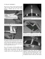
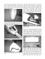
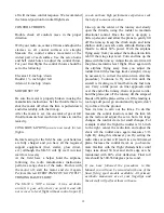
To insert the control rod into the fuselage, tie a
string around the fork and pull the ends together as
shown. Slide the control rod into the fuselage, line
the wires up with the fuselage slots and pull the
string to release the wires through the slots.
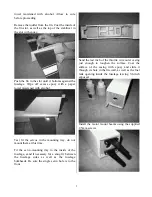
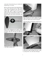
Screw a clevis on each wire of the elevator till
about 1/8-inch of thread remains exposed. Place a
control horn in the clevis and with the control
surface straight locate the control horn so the
adjustment holes are inline with the leading edge
of the control surface. Install the control horn in
this location using the provided screws and
backing plates. Repeat this procedure for the
rudder
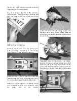
Screw a clevis on the servo end of the elevator
control rod. With the servos centered and the
control surfaces straight adjust the clevis and
install on the servo arm. Mark the rudder wire and
install in the same manner using a “Z” bend.
10


