powerful servos have a higher power consumption
rate than standard servos, for this reason it is
important the battery selected be capable of
supplying the required amperage. In the prototype
we used we used the HITEC #57404 1100ma. The
switch harness must also be of the heavy-duty type;
a lightweight switch may overheat and fail under
high loads.
OPTIONAL REAR RUDDER SERVO
The BRISON 2.4 engine used in the prototype
balances well with pull-pull rudder control. If the
motor you select weighs more you may wish to
install the rudder servo in the bottom of the rear of
the fuselage. This will help compensate for the
additional weight. Use this procedure only if
weight will be a problem. If weight is not a
problem skip this step and proceed to STANDARD
PULL-PULL SERVO.
REAR RUDDER SERVO
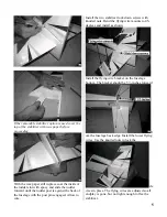
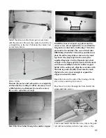
Open a hole in the fuselage bottom just forward of
the flying wire bracket. Fabricate hardwood
mounts and epoxy them in the fuselage. The servo
may be recessed into the fuselage to match your
servo. Install the servo following the manufacture
instructions. With this configuration either pull-
pull or push rod control may be used. Pull-pull is
more precise and the preferred method.
STANDARD PULL-PULL RUDER SERV0
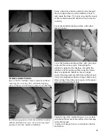
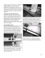
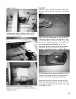
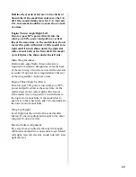
Drill a 3/16-inch hole in the fuselage side, 4-inches
forward of the rudder hinge line 3 ¼-inches down
from the bottom of the stabilizer. Using a small
hand file angle the hole to the path the pull-pull
wire will exit as shown.
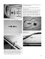
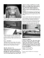
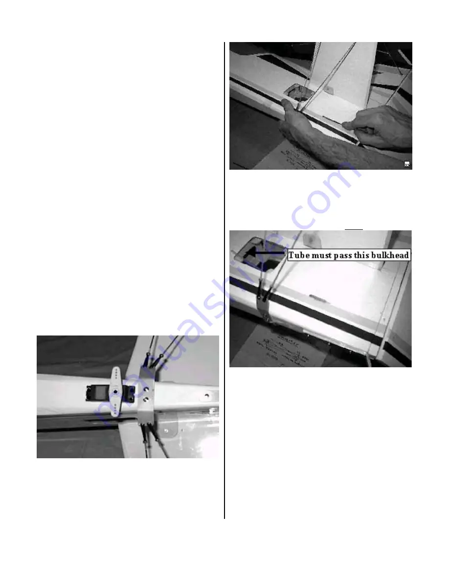
Cut the supplied clear plastic tube in two pieces
approximately 6 ¾-inches long. Epoxy the tube in
place after roughening the last inch to promote
good adhesion. The guide tube should pass through
the fuselage bulkhead in front of the servo well.
The front of the guide tube does NOT get glued.
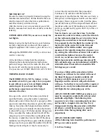
Mount the rudder servo using the manufacture
instructions. The servo control horn should be at
least 2 ¼-inches from outside hole to outside hole.
8


