19
Service and Repair Manual
Model 1400KV/1400BV
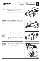
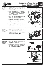
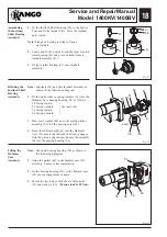
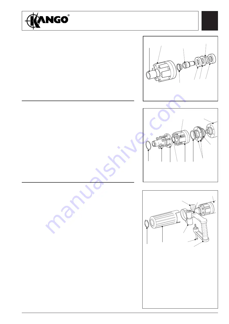
Fig. 34
Fig. 35
Fitting the
Anvil and
Nosepiece
Assemblies
(1400, 1400B)
1.
Fit two new O-rings (20) to the location ring (21).
Fit the location ring (21) to the hammer case (34).
2.
Fit anvil housing assembly (14) to hammer case
(34) and secure using six allen bolts (35)
(
Torque load to 30 Nm
).
Note:
Cut outs on location ring (21) face the striker.
3.
Fit new O-ring (11).
4.
Fit new O-ring (3) to the nosepiece (8).
5.
Fit nosepiece (8) and secure using six allen bolts
(35) (
Torque load to 30 Nm
).
Note:
Lubricate parts as shown in the lubrication
diagram.
1.
Press in the liner (15) into the anvil housing (14).
2.
Lightly lubricate the anvil (13) and fit seal
assembly (12). Insert anvil (13) into the housing
(14) and ensure correct fit.
3.
Fit the recoil ring (16), recoil absorber (17), ring
(18) and catcher housing (19).
Assembly of
the Anvil Unit
(1400, 1400B)
19
13
16 17
18
12
14
15
3
35
8
11 14
20
21
20
34
Fitting the
Front Handle
Assembly
(1400, 1400B)
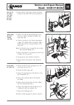
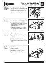
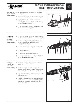
1.
Position the strap casting (26) over the hammer
case (34).
2.
Fit the nose cap (2) over the nosepiece (34)
ensuring correct location of the cut-out over the
strap casting (26). Fit the retaining circlip (1).
3.
Expand the front handle (30) and engage over the
strap casting (26).
4.
Position the handle (30) horizontally to the rear
handle and fit the retaining bolt (27) though the
front handle (30) and secure with washer and
plastic knob (28).
1
2
28
26
27
30
29
34
Fig. 36
35
Summary of Contents for 1400 Series
Page 1: ......


