11
Service and Repair Manual
Model 1400KV/1400BV
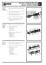
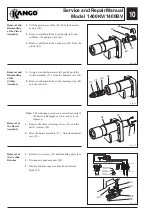
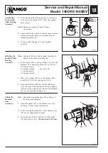
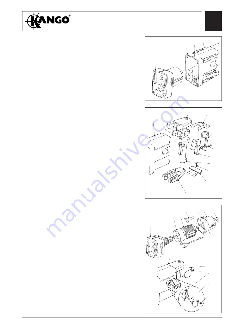
Fig. 14
Removal of
the Motor
Assembly
from the
Bearing
Housing
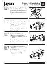
1.
Remove the six Allen bolts (35) from the motor
housing (73) and lift off the motor assembly (A).
A
74
35
73
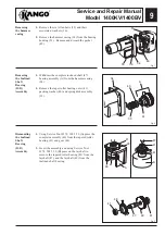
Dismantling
the Rear
Handle
Assembly
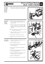
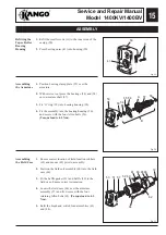
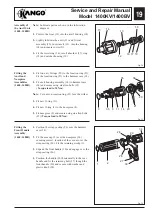
1.
Remove the upper handle locking plate screws
(69) and, using a screwdriver, withdraw the
upper plate (80).
2.
Using a screwdriver, lever off the upper handle
support (79) together with its associated rubber
handle support (78), releasing both sides at the
same time.
Note:
It will be necessary to spread the two locating
clips inside the housing (73).
3.
Remove the handle cover retaining screw (82) and
withdraw the rear grip (81).
4.
Disconnect the wires from the switch (83).
5.
Remove the switch assembly from the handle
(77).
73
79
80
81
83
77
80
79
78
Fig. 16
Fig. 15
Dismantling
the field case
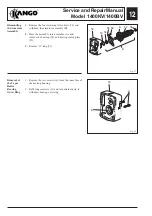
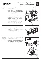
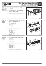
1.
Remove two brush cover retaining screws (76)
and remove the covers (75).
2.
Release the brush spring (68).
3.
Release the locating screws (94) and remove the
brush assemblies (71).
4.
Remove the brush (61) and switch lead (64)
assemblies.
5.
Remove the four Allen bolts (65) and withdraw
the field casing assembly (66).
6.
Remove the baffle (59) from the field case and
withdraw the field coil assembly (60).
7.
Remove the baffle gasket (51).
8.
Remove rubber supports (62) and (63), and (72).
50
51
59 60
61
66
64
62
65
72
82
69
63
75
68
71
94
76
75
Summary of Contents for 1400 Series
Page 1: ......


