18
Service and Repair Manual
Model 710/760
760KV/SV/MV DISMANTLING
Service and Repair Manual
Model 710MV
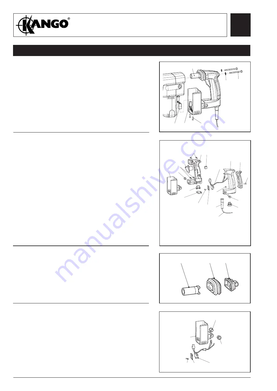
Fig. 26
Fig. 23
Removing
the handle
assembly
1.
Remove two screws (14), two screws (17), two
washers (18) and remove handle assembly.
Note:
It will be necessary to pull hard on the top of
the handle assembly after removal of screws
(17), to remove module (21) with the handle
assembly.
2.
Disconnect RTR loom (26) from field loom (25).
18
14
17
25
26
Fig. 24
Fig. 25
Removing the
handle halves
and speed
control switch
1.
Remove screw (2) and handle cushion.
2.
Remove pivot bolt (4) and pivot nut (3).
3.
Remove handle halves (5 and 6) and lower handle
cover (13).
4.
Remove switch wires from handle half (6).
5.
Remove lower cord clamp (7), upper cord clamp (8)
and foam slug (9).
6.
Remove cord (12) and cord protector (11) from handle
(5).
7.
Remove speed control (10), switch (24) and terminal
block ((115) 710KV/BV) ((126) 710MV) from handle
(5).
8.
Remove screw (27), retaining plate (28) and RTR loom
(26).
Removing the
isolation
module
assembly
1.
Remove upper handle mount (19), isolation
bellows (20) and isolation module (21).
WARNING: Do not dismantle isolation module
(21).
2
3
9
8
4
7
2
5
6
2
1
21
20
19
13
21
24
10
12
26
28
27
11
115 (710KV/BV)
126 (710MV)
Dismantling
the lower
handle cover
1.
Remove two pivot isolators (15), screw (27), retainer
(28) and field lead grommet complete with loom (26)
from lower handle support (13).
13
15
15
13 13
13
Summary of Contents for 710 Series
Page 1: ......


