30
Service and Repair Manual
Model 710/760
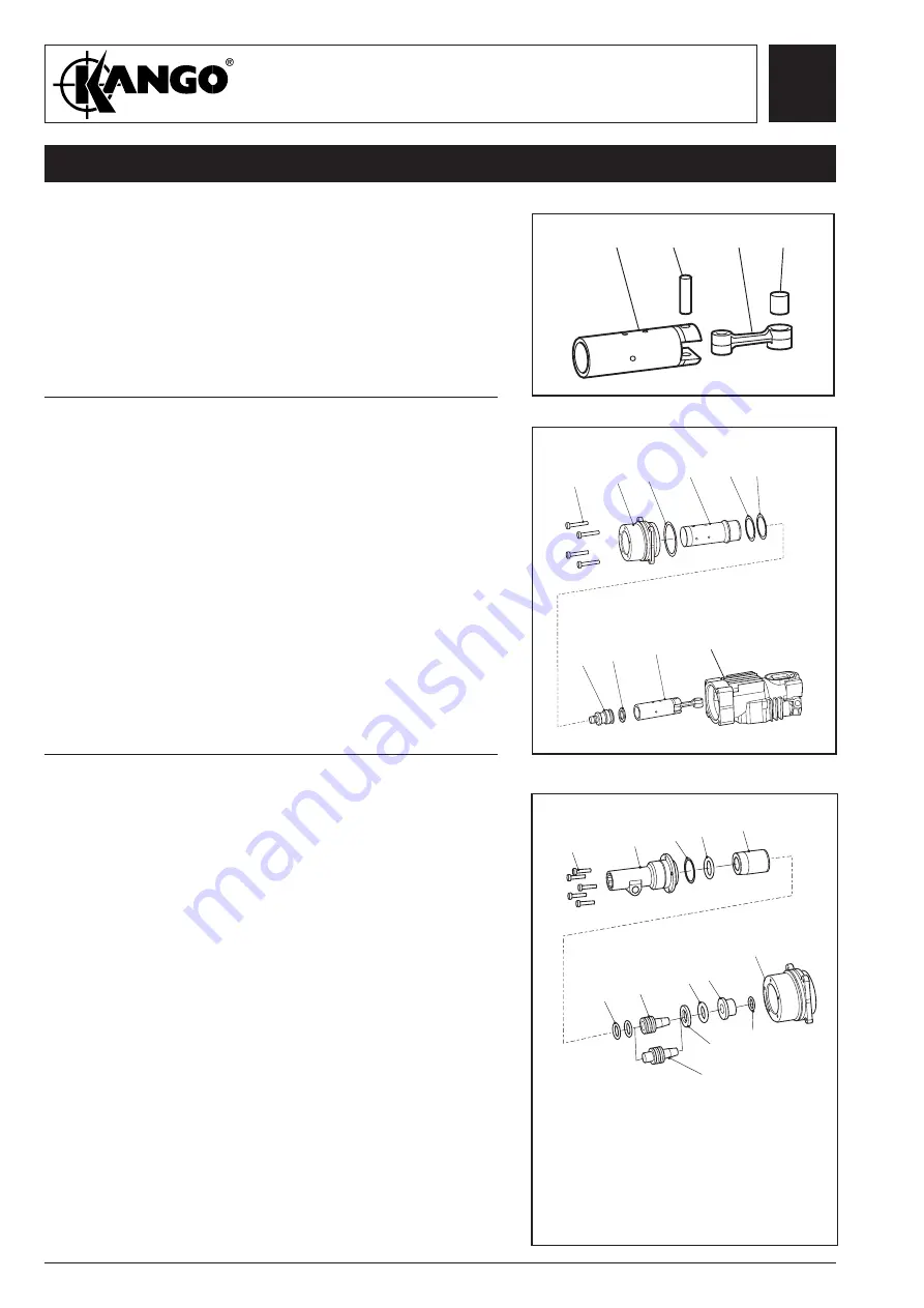
Fig. 49
1.
Fit seals (92) to anvil (91).
2.
Insert anvil assembly to anvil sleeve (93).
3.
Fit O-ring (87) to catcher (88).
4.
Assemble to transmitter housing.
- catcher assembly (87 and 88)
- buffer ring (89)
- recoil transfer ring (90)
- anvil sleeve assy (91-93)
- O-ring (95)
5.
Fit O-ring (94) into nosepiece (96).
6.
Secure nosepiece to transmitter housing (85) with
screws (101)
torque load to 10Nm.
Assembling
the nosepiece
101
96
95 94
93
92
91
(710KV)
91
(710BV)
90
89 88
87
85
Service and Repair Manual
Model 710KV/710BV
710KV/710BV ASSEMBLY
Fig. 47
Fig. 48
1.
Fit bearing (74) into connecting rod (114).
2.
Position connecting rod (114) to piston (77) and
fit gudgeon pin (76) to secure.
Assembling
the piston
1.
Assemble the following items to the transmitter
housing (85):
- O-ring (84)
- barrel (83)
- washer (82)
- shim (81)
- striker (79)
- striker seal (78)
- piston assembly (77)
2.
Fit the barrel assembly and transmitter housing
assembly (85) to top housing (73), and secure
with four screws (86)
torque load to 15Nm
.
Assembling
the barrel
77
76
114
74
86
85 84
83
81
79 78
77
82
73
Summary of Contents for 710 Series
Page 1: ......


