38
Service and Repair Manual
Model 710/760
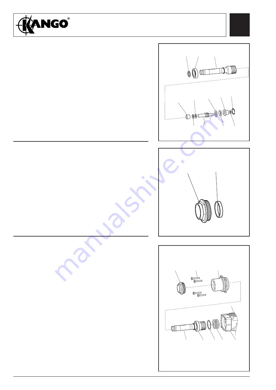
Fig. 70
1.
Fit the following items to driver (110):
- junk ring (109)
- anvil (107) complete with seals (108)
- recoil transfer ring (106)
- buffer ring (105)
- catcher housing (104) complete with O-ring (103)
- wire ring (102)
2.
Fit bearing (111), circlip (112) to driver assembly.
Assembling
the driver
111
112
110
109
108
106 104
108
107
105 103
102
Service and Repair Manual
Model 760MV
Fig. 71
1.
Press seal (113) into nosepiece (114).
Assembling
seal to
nosepiece
Fig. 72
Assembling
the driver
1.
Fit driver assembly (110) to bearing housing.
Assemble washer (97) and spring (96) to spline end
of driver (110).
2.
Locate bearing housing assembly (100/110) into
top housing (79), ensuring that splines locate into
top housing.
3.
Secure with 4 screws (115).
Torque to 15 Nm.
4.
Screw on nosepiece (114) to bearing housing (100),
torque to 50 Nm
.
113
114
114
115
100
110
111
97 96
79
Summary of Contents for 710 Series
Page 1: ......


