12
PAGE
Repair Instructions
K 350
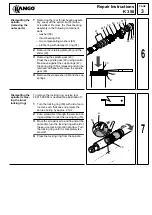
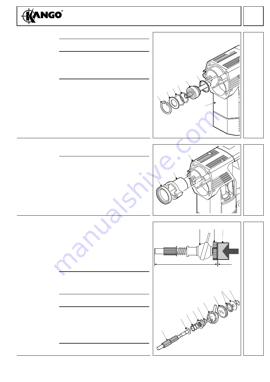
Assembling the
angle drive
1
Insert the support ring (71).
2
Grease the shaft (82) and insert into the
gear box (27) by turning it slightly.
3
Insert the disks (72 &73).
Note: Depending on the tolerance of the
bearing, two or three disks (72 &73) are
needed. For assembly, use the same
amount of disks as removed.
4
Insert the locking washer (67) such that
the lugs face the bearing (see illustration).
Mounting the
spindle bearing
1
Press the sintered bearing (69) into the
bearing housing (70).
2
Insert the bearing housing (70) into the
gear box (27).
Note: Do not press in the bearing hous-
ing (70) completely for easier mounting of
the back shaft (29) and the cylinder (40).
Caution: Care must be taken to ensure
the correct positioning of the bearing
housing (70).
Assembling the
back gear shaft
1
Fit the following parts onto the back of re-
duction gear shaft (29) in the following or-
der:
– disk (31)
– spring (32)
– coupling sleeve (33)
– disk (34)
– tumble drive (35)
2
Press on the reduction gear (36) with
0.05 mm to the tumble drive.
Caution: the smooth surface must face
the tumble drive (35).
3
Lightly grease the thrust bearing (30) and
insert it into the reduction gear (36).
4
Fit the disk (30) and check the distance:
– if the distance is more than 100.5mm, do
not fit the disk (30).
– if the distance is less than 100.5mm fit
another disk (30) and check the dis-
tance again.
5
Push on the O-ring (87).
67
66
82
71
27
72
73
7
69
70
27
8
X
0,5 mm
35
36 30
29
31
32
33
34
35
36
87
30
9
Summary of Contents for K 350
Page 1: ......


