background image

            Technical manual


KANMED Operatherm OP3 

Page 

33 

of 

34


Guidance and manufacturer’s declaration - electromagnetic immunity 

 
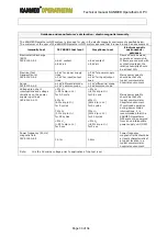
The KANMED Operatherm OP3 system is intended for use in the electromagnetic environment specified below. 
The customer or the user of the KANMED Operatherm OP3 system assures that it is used in such an environment. 

immunity test 

IEC 60601 test level 

Compliance level 

Electromagnetic 

environment - 

guidance 

Electrostatic discharge 
(ESD) 
IEC 61000-4-2 

±6 kV contact 
±8 kV air 

±6 kV contact 
±8 kV air 

Floors should be wood, 
concrete or ceramic tile. 
If floors are covered with 
synthetic material, the 
relative humidity should 
be at least 30% 

Electrical fast 
transient/burst 
IEC 61000-4-4 

±2 kV for power supply 
lines 
±1 kV for input/output 
lines 

±2 kV for power supply 
lines 
±1 kV for input/output 
lines 

Surge 
IEC 61000-4-5 

±1 kV differential mode 
±2 kV common mode 

±1 kV differential mode 
±2 kV common mode 

Mains power quality 
should be that of a 
typical commercial or 
hospital environment 

Voltage dips, short 
interruptions and voltage 
variations on the power 
supply input lines 
IEC 61000-4-11 

<5% U

T  

(>95% dip in U

T

 ) 

for 0,5 cycle 
 
40% U

T  

(60% dip in U

T

 ) 

for 5 cycles 
 
70% U

T  

(30% dip in U

T

 ) 

for 25 cycles 
 
<5% U

T  

(>95% dip in U

T

 ) 

for 5 sec 
 

<5% U

T  

(>95% dip in U

T

 ) 

for 0,5 cycle 
 
40% U

T  

(60% dip in U

T

 ) 

for 5 cycles 
 
70% U

T  

(30% dip in U

T

 ) 

for 25 cycles 
 
<5% U

T  

(>95% dip in U

T

 ) 

for 5 sec 
 

Mains power quality 
should be that of a 
typical commercial or 
hospital environment. 
If continued operation 
during power mains 
interruptions, it is 
recommended that the 
KANMED Operatherm 
OP3 system be powered 
from an uninterruptible 
power supply unit (UPS)  

Power frequency (50 Hz) 
magnetic field 
IEC 61000-4-8 

3 A/m 

3 A/m 

Power frequency 
magnetic fields should be 
at levels characteristic of 
a typical location in a 
typical commercial or 
hospital environment 

Note:


U

is the AC mains voltage prior to application of the test level 

Summary of Contents for Operatherm OP3

Page 1: ...d this manual carefully Manufactured by KANMED AB Gårdsfogdevägen 18B SE 168 66 Bromma Sweden Tel 46 8 56480630 Fax 46 8 56480639 E Mail info Kanmed se Web www Kanmed se This manual is valid for KANMED Operatherm OP3 system serial number 0001 08 and above with Software version 1 1 or higher and Service Software 1 3 or higher Subject to changes ...

Page 2: ...nical Data menu 16 Control Unit Summary 16 Control Unit Calibration Data 16 Heating Pad Data Summary 17 Heating Pad Calibration Data 17 System Measurements 17 Control Unit Calibration Check 18 Log Data Menu 18 Control Unit Log 18 PAD Log 19 Special operation workshop level only 20 Control Unit RE Calibration 20 8 TROUBLE SHOOTING 21 Function Supervision and Alarms 21 Alerts 21 Medium severity alar...

Page 3: ...Latest version of the user manual and information about accessories can be found at www Kanmed se 2 EXPLANATION OF SYMBOLS USED Green LED Mains Power indicator Increase temperature or change highlighted selection in MENU Start Stop button Decrease temperature or change highlighted selection in MENU Red Orange LED Error Indicator MENU Select main MENU or change highlighted selection in MENU Alarm S...

Page 4: ...ent safety Only original parts may be used The Heating Pad cable may not be altered in length or repaired in any way If damaged the complete Heating Pad must be replaced Compatibility Only KANMED OP3 series Heating Pads can be used with Operatherm OP3 Control Unit The Operatherm OP3 system is NOT compatible with KANMED OP200 series Heating Pads EMC Operatherm OP3 needs to be installed and put into...

Page 5: ...ncludes Pad Hanger mains cord and instruction manual Factory set to 220 240V AC 50 60 Hz OP3 115 Control Unit As above but set to 100 120 AC 50 60 Hz OP3 100 Control Unit As above but set to 100V AC 50 60 Hz OP3 104 104 cm Heating Pad 1040 x 450 mm 8 elements 200W X Ray translucent Standard Heating Pad Fits most patients Requires two standard Gel Pads OP3 150 150 cm Heating Pad 1500 x 450 mm 8 ele...

Page 6: ... Power board OP303 3 300 004 Power transformer the large power transformer 2 x 28 6 V 300 VA 300 005 Power transformer electronics power supply transformer 10 3 V 9 VA 300 006 Mains power intake With RF filter 300 007 Connector Saver 37 pin F F 300 008 CU Rear panel excl label 300 011 Cable kit Internal control unit cable kit 300 012 CU Handle 300 013 CU Bottom plate 300 014 CU Cabinet naked cabin...

Page 7: ... boundaries The calculated temperatures of the eight or four heating pad elements are based on individual simultaneous measurement of the voltage and the current to each of the elements by two independent A D converters From these measurements the elements actual resistance is calculated and compared to the nominal resistance value programmed into the pads PROM memory at calibration The temperatur...

Page 8: ... connection of any intermediate connectors used for the measuring circuits Feeding voltage is fed on different pins than the measuring circuit reducing the risk of measurement errors The common Pad feeding current is fed over eight parallel pins for minimum connector load All input output connections are short circuit proof The Pads connector contains a independent micro processor with the dedicat...

Page 9: ... elements 4 Power 100 W 4 x 25W Dimension L 630 mm W 430 mm H 3 mm Weight 1 6 kg Heating Pad small 50cm Art no OP3 050 No of elements 4 Power 100 W 4 x 25W Dimension L 500 mm W 300 mm H 3 mm Weight 1 4 kg Heating up time Elements inside the Heating Pad about 8 10 minutes from 20 C to 37 C Heating Pad surface about 25 minutes from 20 C when tested under conditions of ADEQUATE HEAT DISCHARGE in IEC6...

Page 10: ...nctionality Below is a description of the technical menus and of the additional functions found in the service software Certain procedures e g calibration check and log dump to USB etc can also be performed with the customer software version LOADING SOFTWARE TO THE CU NOTE 1 Before this operation is performed make sure you have one Kanmed approved USB memory stick containing the latest version of ...

Page 11: ...the message Updating SW is displayed the left and right arrow buttons can be released The Ok message indicate that the new software has been successfully loaded 5 When the Stand by screen is displayed disconnect the mains power and remove the USB memory stick from the Control unit Reconnect the mains power and let the system boot as normal The new software has now been loaded into the system The s...

Page 12: ...r format HH MM SS Navigate by pressing the or buttons to highlight the desired digit to be changed and press down arrow to alter the value of the digit Enter saves the new setting and returns the system to the System Settings menu Menu up arrow ignores any change and returns the system to the System Settings menu NOTE up arrow menu exits the function and returns the system to the System Settings m...

Page 13: ... with the Customer Software Version 1 Fit the USB memory stick into the internal USB connector 2 Select Menu Settings Logs to USB Press Enter 3 The message WritingLogs are displayed as long as the writing process continues Leave the system it will normally take a few minutes 4 When the writing process is completed the WritingLogs message disappears The USB stick can now be safely removed ...

Page 14: ... the CU or the PAD Data example from the CU session log file D OPERAT Log 0 Start time Fri Jul 11 14 26 03 2008 End Time Fri Jul 11 14 26 16 2008 Time 13 Total Time 13 Sessions 1 Pad Mode 0 Energy 0 Max Temp 26 06 Min Temp 24 78 Alarm 55 Fri Jul 11 14 26 16 2008 Log 1 Start time Fri Jul 11 14 27 56 2008 End Time Fri Jul 11 14 28 52 2008 Time 56 Total Time 69 Sessions 2 Pad Mode 0 Energy 2 Max Temp...

Page 15: ...p 39 Temp 38 32 Avg Temp 32 04 Max Temp 39 63 Log 3 Time Tue Sep 8 14 34 51 2009 Pad 00004 Desired Temp 39 Temp 37 74 Avg Temp 31 72 Max Temp 39 02 Etc Data example from the file RL OPERA Note normally a very large file Log 0 Time Tue Sep 8 14 35 21 2009 Pad 00004 Desired Temp 39 Temp 39 39 Avg Temp 32 65 Max Temp 40 72 DebugLog Pad 2 CurTemp 40 3127 R 31 67 Po 96 Pad 3 CurTemp 37 7483 R 31 46 Po ...

Page 16: ... SW version data calibration data etc These functions are exclusively designed for technical staff and maintenance personnel NOTE Also available in the Customer Software version Control Unit Summary Information of SW version Calibration information Running hours and No of system starts operating sessions Menu up arrow returns the system to the Technical data menu NOTE Also available in the Custome...

Page 17: ...re This function is also available in the Customer Software version System Measurements This function measures each of the eight channels separately for deep analyze of the system measurement accuracy and the condition of each of the elements in the connected heating pad Press the or buttons to change the channel to study v down arrow changes to a screen where all 8 channels are shown simultaneous...

Page 18: ...should correspond to the adapters reference resistance displayed on top of the screen within 0 03 ohm If the error is larger than this it will display a red marking over the reading otherwise a green Press MENU to exit NOTE If one or several of the readings exceeds 0 03 ohm leave the unit running for at least 10 15 minutes and check again If one or several of the reading is still just outside limi...

Page 19: ...lay the logs of the connected PAD Press or to step through the different log pages Press MENU to exit NOTE The CU must first have been started in normal operation performed a self test with the PAD connected in order to read these logs This function is also available in the Customer Software version ...

Page 20: ...rompt for the second calibration adapter to be inserted note two separate adapters are mandatory for a control unit re calibration Approximately 5 minutes after the second adapter has been fitted the verification process is finished and the system returns steady values indicated by the red or green markings of each of the readings the readings the calculated resistance for each channel should corr...

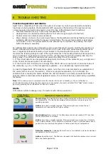
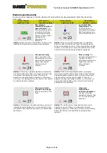
Page 21: ...it is feeding more energy than 25000 Ws over a period of 30 minutes to any of the elements e g error in the temperature regulation or an abnormally high thermal load In case the Operatherm OP3 indicates an alarm note the error code indicated see explanation of the codes further down in this section If there is a logical explanation try to eliminate the condition that is causing the alarm Restart t...

Page 22: ...ing The average temperature of the Pad has had a calculated temperature higher than the set value during 5 minutes Action If there is a logical explanation something has accumulated the heat just reset the alarm and the system will operate as usual If there is no apparent unusual operating condition or the alarm re occurs the Heating Pad or the Control Unit should be analyzed and or replaced Actio...

Page 23: ...onents faulty memory circuits or software error The Heating Pad has corrupted software Probably caused by defective components faulty memory circuits or software error Action The Control Unit should be analyzed by an authorised technician Action The Heating Pad should be analyzed by an authorised technician The Heating Pad connector is not properly fitted or damaged The Heating Pad is not correctl...

Page 24: ...set the alarm and restart the unit Check the actual temperature under the patient If there is no apparent unusual operating condition e g the Pad being heated by another external device the Heating Pad and the Control Unit should be analyzed and or replaced The A D converter used to calculate Pad temperature reports inconsistency Power loss has occurred during normal operation Action Reset the ala...

Page 25: ...e reference resistance in the calibration adapter and display the result on the screen Leave the system running for about 5 minutes If the Control Unit measure the correct resistance within tolerance the measured value turns green if the measurement is outside of acceptable tolerance the value turns red b Check of Mains Failure alarm Remove the power cord from the Control Unit during normal operat...

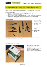
Page 26: ...lways work in an anti static environment Use an ESD protection bracelet attached to the earth pin on the back of the control unit Tools required Torx key Size T10 pref magnetic note Screwdriver slotted type 6 mm Box cutter knife and or a Pair of scissors ESD protection bracelet note If no magnetic torx key is available a standard torx key can be used with a small magnet e g neodymium type attached...

Page 27: ...removal of the circuit board Do not pull directly on the cables Use a screw driver to carefully pry the connector locking device open Then pull the connectors straight up Remove the 4 screws that hold the circuit board in place Carefully pry the connector locking device open Slide the PC board to the side and carefully remove it If the Display assembly or the main board needs to be removed pls pro...

Page 28: ... of 34 3 Remove the 4 screws that holds the display assembly 4 Remove the connector saver 5 Carefully loosen the display assembly from the cabinet 6 Remove the flat cable and the earth cable 7 Loosen the 4 main board screws 8 Remove the main board ...

Page 29: ... order not to damage the components mounted on the flat cable 1 Slide the display assembly carefully in under the plastic protective sleeve 2 Mount the display assembly Fit the connector saver adjust then the position and tighten the four main board screws 3 Mount the rubber frame Be observant to position the cavities over the screw heads Adjust the frame for a nice close fit Carefully apply a sma...

Page 30: ... not possible to replace the board either since it is factory calibrated with the pad and the connecting cable Only the casing can be replaced if damaged Remove all screws 4 pcs from the bottom plate of the Connector assembly Remove the bottom part Replace the PAD Connector Casing if required and refit the screws Pls observe to use proper ESD protection ...

Page 31: ...the written consent of KANMED The product has been modified adjusted or repaired without following the written KANMED guidelines The unit has been used for other purposes than the intended use misused dropped or in any other way been abused Warranty claims must be confirmed in writing KANMED is not responsible in any way for any damages arising from deviation from the intended use neglect of safet...

Page 32: ...oltage power supply network that supplies buildings used for domestic purposes Recommended separation distances between portable and mobile RF communications equipment and the KANMED Operatherm OP3 system The KANMED Operatherm OP3 system is intended for use in the electromagnetic environment in which radiated RF disturbances are controlled The customer or the user of the KANMED Operatherm OP3 syst...

Page 33: ...ferential mode 2 kV common mode 1 kV differential mode 2 kV common mode Mains power quality should be that of a typical commercial or hospital environment Voltage dips short interruptions and voltage variations on the power supply input lines IEC 61000 4 11 5 UT 95 dip in UT for 0 5 cycle 40 UT 60 dip in UT for 5 cycles 70 UT 30 dip in UT for 25 cycles 5 UT 95 dip in UT for 5 sec 5 UT 95 dip in UT...

Page 34: ...es m Field strengths from fixed RF transmitters as determined by an electromagnetic site survey should be less than the compliance level in each frequency range Interference may occur in the vicinity of equipment marked with the following symbol Note 1 At 80 MHz and 800 MHz the higher frequency range applies Note 2 These guidelines may not apply in all situations Electromagnetic propagation is aff...

Reviews: