background image

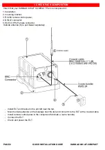
QUICK INSTALLATION GUIDE 

KANNAD 406 AF-COMPACT

PAGE 3 

Determine the lo

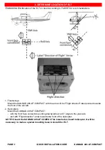
cation of the ELT on board according to FAR/RTCA recommendations.
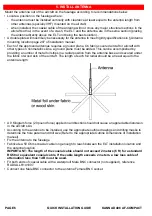
1. Fixed wings

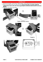
Mount the KANNAD 406-AF COMPACT with the arrow of the "Flight direction" label pointed towards 
the front of the aircraft.

2. Helicopters

Mount the KANNAD 406 AF COMPACT:
- with the front face connectors pointing downwards at a 45° angle to the yaw axis;
- and with "Flight direction" arrow towards the front of the helicopter.

NOTE: Should the KANNAD 406 AF COMPACT be installed on board helicopter, it will be 
necessary to make a special mounting base to install the ELT.

2. DETERMINE LOCATION OF ELT

Summary of Contents for 406 AF-COMPACT

Page 1: ...DOC07089A 0144618A...

Page 2: ...12 connector 5 SUB D 9 Pts Female connector Outside antenna 6 is purchased separately Install ELT and bracket in the aircraft near the tail Mount outside antenna on the fuselage near the tail and con...

Page 3: ...ion label pointed towards the front of the aircraft 2 Helicopters Mount the KANNAD 406 AF COMPACT with the front face connectors pointing downwards at a 45 angle to the yaw axis and with Flight direct...

Page 4: ...ion manual Inner holes 1 2 3 4 shall be preferred 2 If the aircraft structure is not solid enough to withstand a 500 kg traction on the bracket a reinforcement plate not supplied should be installed a...

Page 5: ...ion arrow pointed towards the front of the aircraft 2 Slide the self stripping strap throught the buckle Ensure the buckle is correctly positioned indifferently on righ or left side of ELT regarding t...

Page 6: ...ccomplished by providing a number of metal foil strips in a radial position from the antenna base and secured under the fabric or wood skin of the aircraft The length of each foil radial should be at...

Page 7: ...k or the RC200 as a guide Drill the 4 marked holes diameter depending on rivets bush used Install the RC200 by fitting it into the cutout Secure the RC200 4 rivets bush recommended 2 Below the instrum...

Page 8: ...he BNC connector of the front panel 2 Connect the DIN12 connector of the Remote Control Panel cable to the DIN 12 socket of the front panel 3 Set the 3 position switch of the front panel to ARM Perfor...

Reviews: