QUICK INSTALLATION GUIDE
KANNAD 406 AF-COMPACT
PAGE 6
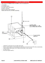
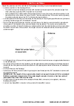
Mount the antenna out of the aircraft on the fuselage according to recommendations below.
• Locate a position on the fuselage where:
- the antenna must be installed vertically with clearance at least equal to the antenna length from
other antennas (specially VHF) mounted on the aircraft,
- when installed, the coaxial cable of the antenna will not cross any major structural sections in the
aircraft so that, in the event of a crash, the ELT and the antenna are in the same section (placing
the antenna directly above the ELT unit being the best solution)..
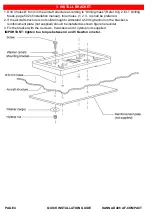
• A double plate will most likely be necessary for the antenna to meet rigidity specifications in § Antenna
mounting location page 207 of installation manuel.
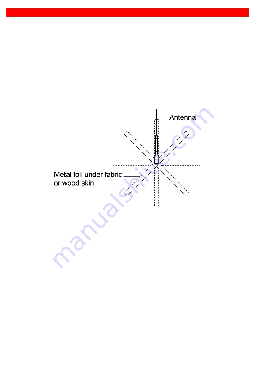
• Each of the approved antennas requires a ground plane. On fabric-covered aircraft or aircraft with
other types on nonmetallic skins, a ground plane must be added. This can be accomplished by
providing a number of metal foil strips in a radial position from the antenna base and secured under
the fabric or wood skin of the aircraft. The length of each foil radial should be at least equal to the
antenna length.
• A 9 Kilogram force (20 pound force) applied in all direction should not cause an appreciable distorsion
in the aircraft skin.
• According to the antenna to be installed, use the appropriate outline drawings and drilling masks to
determine the hole patern and drill size (Refer to the appropriate Outline Dimensions of installation
manuel).
• Fix the antenna to the fuselage
• Fabricate a 50 Ohms coaxial cable long enough to reach between the ELT installation location and
the antenna location.
IMPORTANT: The length of the coaxial cable should not exceed 2 meters (6 ft) for a standard
RG58 or equivalent coaxial cable. If the cable length exceeds 2 meters, a low loss cable of
attenuation less than 1 dB must be used.
• Fit both ends of coaxial cable with a waterproof Male BNC connector (not supplied), reference
RADIALL R141007.
• Connect one Male BNC connector to the antenna Female BNC socket.
5. INSTALL ANTENNA
Summary of Contents for 406 AF-COMPACT
Page 1: ...DOC07089A 0144618A...

