background image

QUICK INSTALLATION GUIDE 

KANNAD 406 AF-COMPACT

PAGE 7 

Determine RC200 location on or below the instrument panel (be sure the location meets the 
requirements established in RTCA-DO-183) in an area that is not directly exposed to sun rays.

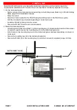
1. On the instrument panel

- Mark a cutout on the instrument panel according to the Drilling mask (Refer to § 4. RC200 Drilling 

Mask, page 504 of installation manuel).

- Make the cutout.
- Mark the 4 holes needed for the RC200 using the drilling mask or the RC200 as a guide.
- Drill the 4 marked holes, diameter depending on rivets bush used.
- Install the RC200 by fitting it into the cutout.
- Secure the RC200 (4 rivets bush recommended).

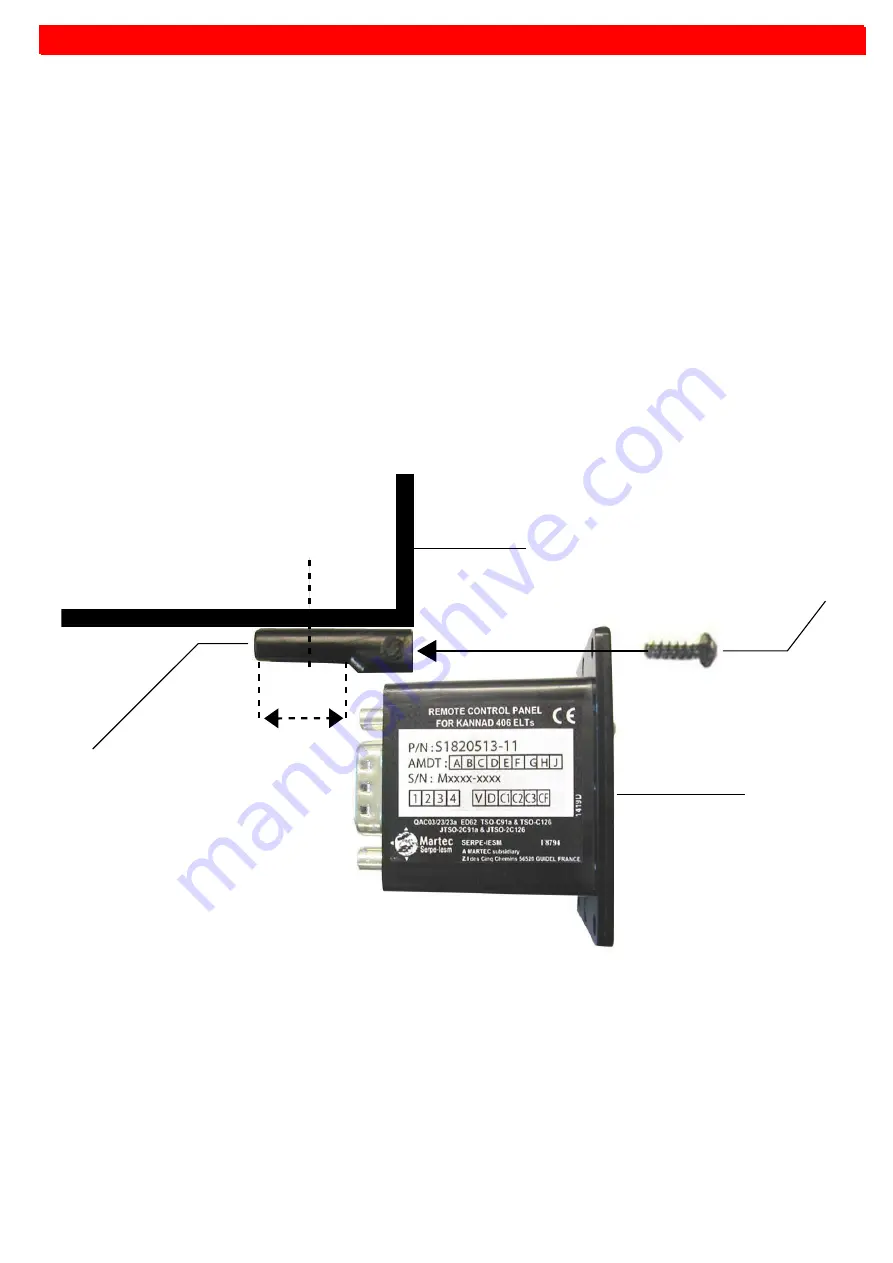
2. Below the instrument panel

- According to the "area to be drilled" (1) of the mounting tray (3), determine the location of the screws 

or rivets (2) used to secure the mounting tray (3) to the instrument panel (4).

- Drill 2 holes on the mounting tray and on the instrument panel, diameter depending on screws or 

rivets used.

- Secure the mounting tray (3) to the instrument panel (4).
- Secure the RC200 (5) to the mounting tray (3) with the 2 screws (6) supplied (torque 0.8 Nm).

INSTRUMENT PANEL

1

2

3

4

5

6

6. INSTALL RCP

Summary of Contents for 406 AF-COMPACT

Page 1: ...DOC07089A 0144618A...

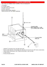
Page 2: ...12 connector 5 SUB D 9 Pts Female connector Outside antenna 6 is purchased separately Install ELT and bracket in the aircraft near the tail Mount outside antenna on the fuselage near the tail and con...

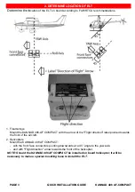
Page 3: ...ion label pointed towards the front of the aircraft 2 Helicopters Mount the KANNAD 406 AF COMPACT with the front face connectors pointing downwards at a 45 angle to the yaw axis and with Flight direct...

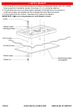
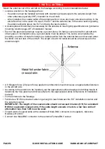
Page 4: ...ion manual Inner holes 1 2 3 4 shall be preferred 2 If the aircraft structure is not solid enough to withstand a 500 kg traction on the bracket a reinforcement plate not supplied should be installed a...

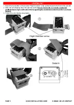
Page 5: ...ion arrow pointed towards the front of the aircraft 2 Slide the self stripping strap throught the buckle Ensure the buckle is correctly positioned indifferently on righ or left side of ELT regarding t...

Page 6: ...ccomplished by providing a number of metal foil strips in a radial position from the antenna base and secured under the fabric or wood skin of the aircraft The length of each foil radial should be at...

Page 7: ...k or the RC200 as a guide Drill the 4 marked holes diameter depending on rivets bush used Install the RC200 by fitting it into the cutout Secure the RC200 4 rivets bush recommended 2 Below the instrum...

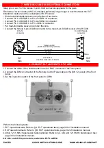
Page 8: ...he BNC connector of the front panel 2 Connect the DIN12 connector of the Remote Control Panel cable to the DIN 12 socket of the front panel 3 Set the 3 position switch of the front panel to ARM Perfor...

Reviews: