background image


CONTENTS 


  1. NEEDLES & THREADING THE MACHINE 

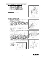
10. THE ADJUSTMENT OF CUTTING DEVICE 

1-1 Needles ···························································· 1 

1-2 Replacing the needle ······································· 1 

1-3 Threading the machine ··································· 1 

  2. MACHINE SPEED 

2-1 Machine speed & direction in which the machine 

pulley runs  ······················································ 2 

2-2 Motor & belt  ···················································· 2 

 3. LUBRICATION 

3-1 Oil ···································································· 3 

3-2 Oiling ······························································· 3 

3-3 Replacing the oil and the oil element ············· 3 

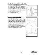
  4. SEWING MACHINE INSTALLATION 

4-1 Cutting the machine table  ······························ 4 

4-2 Installing the machine ···································· 5 

 5.  TIMING OF THE LOOPER TO THE 

NEEDLES 

5-1 Angle and height for installing the looper  ····· 5


5-2 Looper left-to-right movement ························ 6 

5-3 Looper setting distance  ··································· 6 

5-4 Needle height ·················································· 7 

5-5 Needle/looper front-to-back relationship  ········ 7 

5-6 Changing the looper orbit  ······························· 8 

5-7 Changing the amount of the looper front-to-back 

movement ························································ 8 

  6. FRONT AND REAR NEEDLE GUARDS 

6-1 Position of the needle guard (rear) ················· 9 

6-2 Position of the needle guard (front)  ················ 9 

  7. FEED DOGS & STITCH LENGTH 

7-1 Feed dog height & tilt  ··································· 10 

7-2 Stitch length ·················································· 11 

7-3 Differential feed ············································ 11 

  8. PRESSER FOOT 

8-1 Presser foot pressure  ····································· 12 

8-2 Position of the presser foot & foot lift ··········· 12 

  9. STITCH FORMATION 

9-1 Position of the needle thread guides  ············ 13 

9-2 Position of the thread guide on the needle 

thread take-up  ··············································· 13 

9-3 Position of the needle thread guard  ············· 13 

9-4 Position of the thread guide of the looper thread 

take-up ··························································· 14 

9-5 Position of the looper thread take-up  ··········· 14 

10-1 The specifications for C and PC type  ··········15 

10-2 Lubrication  ···················································15 

10-3 Adjustment of cutting width ·······················15 

10-4 Replacement for folder ································16 

10-5 Adjustment of knife pressure  ······················16 

10-6 Adjustment of the front presser foot pressure 

········································································16 

10-7 Replacement of upper knife  ························17 

10-8 Replacement of stationary knife ·················17 

10-9 The way of remove of cutting device  ···········18 

11. ADJUSTING THE REAR PULLER 

11-1 Position of the hand lever and the stopper ·19 

11-2 To adjust the puller pressure  ······················19 

11-3 To adjust the feeding amount of the rear puller 

········································································19 

12. REPLACING THE TIMING BELT 

12-1 Marks on the timing belts ···························20 

12-2 To remove the timing belt ···························20 

12-3 To place the timing belt  ·······························21 

13. CLEANING THE MACHINE


······················21


B

B

L

L

X

X

s

s

e

e

r

r

i

i

e

e

s

s


Summary of Contents for BLX2202PC

Page 1: ...INSTRUCTION Industrial Sewing Machines BLX2202 BLX2202C BLX2202PC First published September 2003 No 030159...

Page 2: ...e 2 Before starting the machine check to make sure the pulley cover safety cover etc are secured 3 Before adjusting cleaning threading the machine or replacing the needle be sure to turn off the power...

Page 3: ...length 11 7 3 Differential feed 11 8 PRESSER FOOT 8 1 Presser foot pressure 12 8 2 Position of the presser foot foot lift 12 9 STITCH FORMATION 9 1 Position of the needle thread guides 13 9 2 Position...

Page 4: ...e sure to turn off the machine A clutch motor continues running for a while after the machine is turned off Therefore keep on pressing the pedal until the machine stops 1 3 Threading the machine Threa...

Page 5: ...utch motor Belt M type V belt Select the proper motor pulley according to the machine speed refer to the motor pulley outer diameter on the table below Adjust where to position the motor by pressing t...

Page 6: ...he oil after the first 250 hours of operation To replace the oil follow the procedures below 1 Remove the V belt from the motor pulley and then remove the machine from the table 2 Remove screw D and t...

Page 7: ...4 SEWING MACHINE INSTALLATION 4 1 Cutting the machine table Cut the diagonally shaped area for the C PC type 4 B BL LX Xs se er ri ie es s...

Page 8: ...the rubber cushions Install the chute for the C PC type see below 5 TIMING OF THE LOOPER TO THE NEEDLES 5 1 Angle and height for installing the looper To obtain the proper angle and height insert the...

Page 9: ...holding the timing pulley upper by hand 5 3 Looper setting distance Set the looper so that the distance from the point of the looper to the center of the needle bar is 6mm when the looper is at its fa...

Page 10: ...ch needle drops into the center of each needle hole 5 5 Needle looper front to back relationship The point of the looper is 0 5 1mm above the top of the left needle s eye on the back side of the needl...

Page 11: ...ooper moves to the left The needle extremely touches the back of the looper causing needle breakage 5 7 Changing the amount of the looper font to back movement The clearance between the point of the l...

Page 12: ...5mm when the point of the looper has reached the center of the right needle from the extreme right end of its travel When the point of the looper has reached the center of the left needle make sure th...

Page 13: ...d dogs up or down Tilt Remove the cover from the rear side of the bed Loosen screw D from hole C with a 2 5mm hex wrench When the feed dogs are at their top of their stroke the feed dogs should be par...

Page 14: ...required position To obtain a feed ratio of 1 1 align lever B with reading C To obtain the normal differential feed raise lever B above reading C To obtain a feed ratio of 1 2 set lever B at 2 Revers...

Page 15: ...resser bar so that the needle can drop correctly to the center of the presser foot needle drop hole Position of the presser foot Loosen screw A Adjust by moving the presser foot left or right while ch...

Page 16: ...and the distance from the center of the shaft to the thread guide of needle thread take up B should be 75mm To make this adjustment loosen screws C and D To tighten the needle thread move needle threa...

Page 17: ...o the front Do not thread the tension disk 9 5 Position of the looper thread take up Thread guide D should be at the center of the groove of looper thread take up A When the point of the left needle h...

Page 18: ...position by dialing the screw F according to the scale on the front needle plate After that tighten the screw L temporary e Turn the hand pulley to position the needle bar at the bottom of its stroke...

Page 19: ...e folder C against the center of needle bar then tighten the screw on the folder C b Positioned the point of back side of front presser foot against the center of the folder C by loosen the screw D c...

Page 20: ...knife a Remove the knife cover base A b Remove the stationary knife B by loosen the screw C then pushing the pressure adjustment dial D c Set the new stationary knife carefully in the stationary knife...

Page 21: ...sen the screw G to make lower position for the support feed dog H e Remove the cutting device bracket in front A positioning pin is fit the cutting device bracket so that move it off with screwdriver...

Page 22: ...yet be sufficient to feed the fabric smoothly To increase the pressure turn adjusting knob D clockwise To decrease the pressure turn adjusting knob D counterclockwise 11 3 To adjust the feeding amoun...

Page 23: ...2 To remove the timing belt 1 Loosen the eight arm cover set screws and the six oil reservoir set screws see the illustration Remove each part 2 Loosen two screws A Remove the handwheel to the right w...

Page 24: ...g the pulley Bring the needle bar down to the bottom of its stroke by hand 4 Then place the belt onto the timing pulley on the upper shaft Tighten two screws A 5 Bring the needle bar up to the top of...

Reviews: