background image


 15 


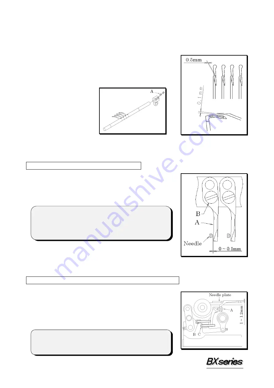
7777----2 Timing of the retainer looper to the needle

2 Timing of the retainer looper to the needle

2 Timing of the retainer looper to the needle

2 Timing of the retainer looper to the needle    

When the needle, moving from the top to bottom of its stroke, enters the triangle of the 
looper thread, the retainer looper should be at the extreme right end of its travel. 
To adjust the retainer looper left to right, loosen screws A first.    With the retainer looper 
at the extreme left end of its travel, set the clearance 
between the retainer looper and the right side of the 
looper at approximately 0.5mm.  Then set the clearance 
between the retainer looper and the top surface of the 
looper blade at 0.1mm.  After this adjustment is made, 
tighten screws A. 


8

ADJUSTING THE NEEDLE GUARD   

8888----1 Position of the needle guard

1 Position of the needle guard

1 Position of the needle guard

1 Position of the needle guard    

When the needle is closest to the needle guard, there 
should be a clearance 0~0.1mm between the right side of 
the needle and needle guard A. 
Adjustment is made by loosening screw B. 


9

ADJUSTING THE FEED DOG & STITCH LENGTH   

9999----1 Feed dog height & tilt

1 Feed dog height & tilt

1 Feed dog height & tilt

1 Feed dog height & tilt    

When the needle bar is at the top of its stroke, the feed 
dog teeth should be 1~1.2mm above the top surface of the 
needle plate.    Adjustment is made by loosening screw A. 
Then check to see if the feed dog teeth is parallel with the 
top surface of the needle plate.    Adjustment is made with 
screws B and C. 


< Note > 

To adjust the standard type of needle guard, after positioning 

the looper holder bracket (see 6-1) adjust the looper by 

loosening the looper set screw.    Then tighten screw B.


< Note > 

When adjusting the height of the feed dog, tilt the looper 

holder toward the front of the machine. 


Summary of Contents for BX Series

Page 1: ...STRUCTION INSTRUCTION Industrial Industrial Industrial Industrial Sewing Sewing Sewing Sewing Machines Machines Machines Machines First published November 1997 No 970112 BX1425P PSM PTV BX1433P PSM PT...

Page 2: ...tenance procedures on this machine 2 Before starting the machine check to make sure the pulley cover safety cover etc are secured 3 Before adjusting cleaning threading the machine or replacing the nee...

Page 3: ...ner looper to the needle 15 8 ADJUSTING THE NEEDLE GUARD 8 1 Position of the needle guard 15 9 ADJUSTING THE FEED DOG STITCH LENGTH 9 1 Feed dog height tilt 15 9 2 Stitch length 16 10 ADJUSTING THE PR...

Page 4: ...eedles UO113GS of Schmetz or Organ Select the proper needle for the fabric and thread Needles and needle size Schmetz Nm75 Nm80 Nm90 Nm100 Nm130 Organ 11 12 14 16 21 2 2 2 2 2 Replacing the needle 2 R...

Page 5: ...g the looper drawing bar To tilt the looper toward the front 1 Bring needle bar A to the top of its stroke 2 Pay out the needle thread from the spool by pressing a finger down on needle threads B 3 Pu...

Page 6: ...3 Threading diagram for BX1425P...

Page 7: ...4 Threading diagram for BX1433P...

Page 8: ...5 Threading diagram for BX1025...

Page 9: ...6 Threading diagram for BX1033...

Page 10: ...7 Threading diagram for BX1425PSM...

Page 11: ...8 Threading diagram for BX1433PSM...

Page 12: ...ulley turns counterclockwise as seen from the end of the machine pulley 3 3 3 3 2 Mot 2 Mot 2 Mot 2 Motor belt or belt or belt or belt Motor 3 phase 2 pole 400W clutch motor Belt M type V belt Select...

Page 13: ...e filter element 3 Replacing the oil and the filter element 3 Replacing the oil and the filter element To extend machine life be sure to replace the oil after the first 250 hours of operation To repla...

Page 14: ...11 5 SEWING MACHINE INSTALLATION 5 5 5 5 1 Cutting the machine table 1 Cutting the machine table 1 Cutting the machine table 1 Cutting the machine table...

Page 15: ...looper holder bracket 1 Angle for installing the looper and position of the looper holder bracket 1 Angle for installing the looper and position of the looper holder bracket 1 Angle for installing th...

Page 16: ...en the looper enters the needle thread loop the point of the looper should be 4mm above the top of the needle s eye To make this adjustment remove the cover first loosen eccentric set screw D and then...

Page 17: ...7 ADJUSTING THE TIMING OF THE RETAINER LOOPER 7 7 7 7 1 Position of the retainer looper 1 Position of the retainer looper 1 Position of the retainer looper 1 Position of the retainer looper Install re...

Page 18: ...needle guard 1 Position of the needle guard 1 Position of the needle guard 1 Position of the needle guard When the needle is closest to the needle guard there should be a clearance 0 0 1mm between the...

Page 19: ...OT 10 10 10 10 1 Presser foot pressure 1 Presser foot pressure 1 Presser foot pressure 1 Presser foot pressure The presser foot pressure should be as light as possible yet be sufficient to feed the fa...

Page 20: ...g To increase the amount loosen nut G and move it to the left To decrease the amount move it to the right 12 ADJUSTING THE STITCH FORMATION 1 1 1 12 2 2 2 1 Thread tension adjustment 1 Thread tension...

Page 21: ...le bar is descending the looper thread eyelet bar should ascend With the looper thread eyelet bar at the bottom of its stroke adjust distance A between the eye on the looper thread eyelet and the loop...

Page 22: ...on the outside to use the lower two spreaders Install any one of cams No 2 to No 9 on the inside to use the upper spreader Thread spreaders eyes marked Following the above procedures automatically pro...

Page 23: ...20 No 5 No 5 No 5 No 5 No 6 No 6 No 6 No 6 No 7 No 7 No 7 No 7 No 8 No 8 No 8 No 8 N N N No 9 o 9 o 9 o 9...

Page 24: ...s stroke adjust the cams so that spreaders K L and M stop moving Adjustment is made by loosening screws C and J see Replacing the cams 2 Position of spreader K With spreader K at the extreme left end...

Page 25: ...he binder 1 Disassembling and reassembling the binder 1 Disassembling and reassembling the binder 1 Disassembling and reassembling the binder To disassemble the binder Remove screw A Remove the binder...

Page 26: ...Position of the upper and lower fingers of the binder 3 Position of the upper and lower fingers of the binder 3 Position of the upper and lower fingers of the binder Position upper and lower fingers s...

Reviews: