background image


 1 


 Note 


When connecting electric cord, make sure to turn off 

the switch of main power source. 

 Note 


Be careful in connecting electric cord A to control box. 

Check the mark of electric cord A and control box. 

Then, connect them. 

1

WIRING   

1111----1 Power Supply Cord

1 Power Supply Cord

1 Power Supply Cord

1 Power Supply Cord    

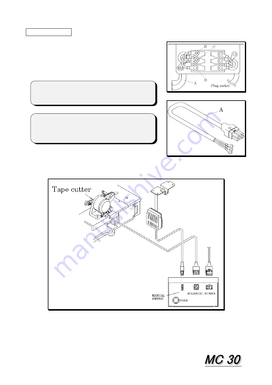
Connect electric cord A to ON/OFF switch of 
machine head.  Connect the cords with blue and 
brown color to 2 of 3 terminal of B, C, D. 
The cord with green/yellow color is earth cord 
which should be connected to earth terminal. 


1111----2 Intermediate Cord

2 Intermediate Cord

2 Intermediate Cord

2 Intermediate Cord    

Connect the cords with referring to the following picture. (also refer to the parts list.) 
After connecting, fix the cords with bands to the proper place under the table. 


Summary of Contents for MC 30

Page 1: ...INSTRUCTION Industrial Sewing Machines First published January 2002 No 020002 ...

Page 2: ...res and save it for later use 1 This instruction manual describes adjustments handling and maintenance procedures on tape cutter 2 Make sure to turn off the power electric and compressed air before adjusting cleaning etc 3 Refer to the parts list as well as this instruction manual when doing the maintenance job 4 The contents described in this instruction manual are subject to change without notic...

Page 3: ... 2 Intermediate Cord 1 2 ADJUSTMENT Electric Type 2 1 Height of Cutter 2 2 2 Overlapping of Cutter 2 2 3 Power of Upper Cutter 2 3 AIR PIPING WIRING Air Type 3 4 AIR PRESSURE 3 5 ADJUSTMENT Air Type 5 1 Height of Cutter 4 5 2 Overlapping of Cutter 4 5 3 Power of Cutter 4 ...

Page 4: ...rd 1 Power Supply Cord Connect electric cord A to ON OFF switch of machine head Connect the cords with blue and brown color to 2 of 3 terminal of B C D The cord with green yellow color is earth cord which should be connected to earth terminal 1 1 1 1 2 Intermediate Cord 2 Intermediate Cord 2 Intermediate Cord 2 Intermediate Cord Connect the cords with referring to the following picture also refer ...

Page 5: ...istance between lower cutter and upper cutter at the top position top dead point During this adjustment do not forget to align between surface G surface of lever F and edge surface of solenoid shaft 2 2 2 2 2 Overlapping of Cutter 2 Overlapping of Cutter 2 Overlapping of Cutter 2 Overlapping of Cutter 1 Loosen screw I then loosen screw J until disappearing of pressurized power of upper cutter 2 Lo...

Page 6: ...egulator 3 AIR PIPING WIRING AIR TYPE Connect the air tube and the electric cords with referring to the following picture also refer to the parts list After connecting fix the air tube and the electric cords with bands onto the proper place under the table 4 AIR PRESSURE Set the air pressure at 4 5 kg cm2 by regulator Do not increase the air pressure over 5 kg cm2 which may cause trouble ...

Page 7: ...t lever L in order to set 24 mm of the distance between lower cutter and upper cutter at the top position top dead point 5 5 5 5 2 Overlapping of Cutter 2 Overlapping of Cutter 2 Overlapping of Cutter 2 Overlapping of Cutter 1 Loosen screw M then loosen screw N until disappearing of pressurized power of upper cutter 2 Loosen screw O then adjust screw P in order to overlap properly between upper cu...

Reviews: