background image

 16 


10

10

10

10----7 Position of the looper thread take

7 Position of the looper thread take

7 Position of the looper thread take

7 Position of the looper thread take----up

up

up

up    

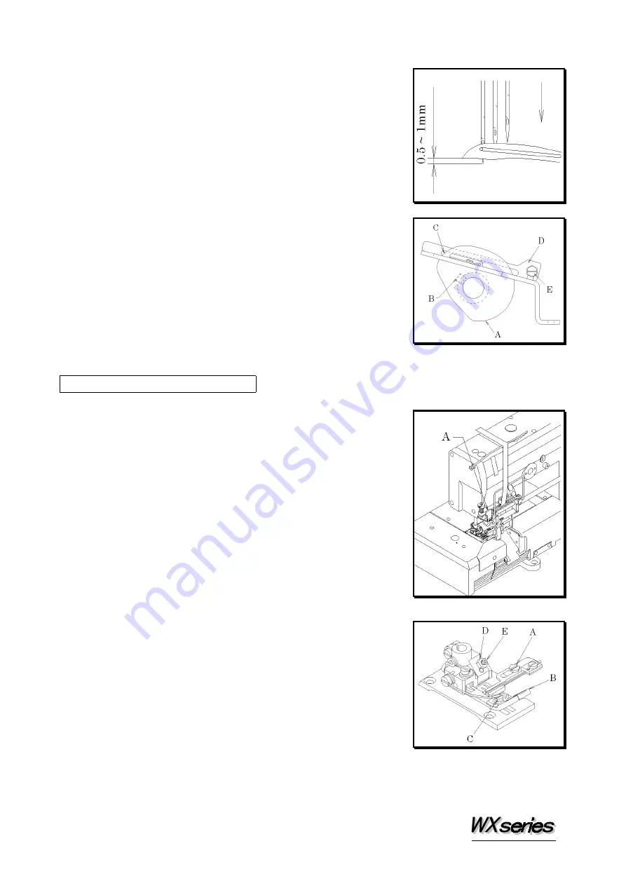
Thread guide D should be at the center of the groove of 
looper thread take-up A.  When the point of the left 
needle has reached 0.5~1mm above the bottom surface of 
the looper blade while the looper is moving from the 
extreme left end of its travel, the looper thread should be 
removed from position C on the looper thread take-up. 
To make this adjustment, loosen screw B and adjust the 
looper thread take-up.  To adjust the height of thread 
guide D, loosen screw E and then align the bottom of the 
slot of thread guide D with the top surface of the bracket. 


11

EMK ELASTIC FEEDER   

11

11

11

11----1 To insert the lace/elastic

1 To insert the lace/elastic

1 To insert the lace/elastic

1 To insert the lace/elastic    

Insert the lace/elastic correctly by referring to the 
illustration.  The rollers are opened by pressing rubber 
adjusting lever A. 

11

11

11

11----2 Lace/elastic guide on the presser foot

2 Lace/elastic guide on the presser foot

2 Lace/elastic guide on the presser foot

2 Lace/elastic guide on the presser foot    

Loosen screw A.  Adjust the position of the tape guide 
according to the needle space and/or width of the tape.  
Adjust the position of upper knife guide B according to the 
hem width cut by the knife.    Install upper knife guide B 
by tightening screw C while checking upper knife guide B 
does not touch the knife. 


11

11

11

11----3 Adjusting the front of the presser foot

3 Adjusting the front of the presser foot

3 Adjusting the front of the presser foot

3 Adjusting the front of the presser foot    

Adjust the front of the presser foot according to the type of 
fabric and/or elastic to be used. 
To sew heavy weight elastic onto the fabric, raise the front 
of the presser foot.    This reduces resistance and feeds the 
fabric smoothly.  Loosen nut D and turn screw E as 
required. 


Summary of Contents for WX Series

Page 1: ...INSTRUCTION Industrial Sewing Machines First published August 1991 Second edition March 1997 No 970016 WX8800 WX8700 LX5801...

Page 2: ...tarting the machine check to make sure the pulley cover safety cover etc are secured 3 Before adjusting cleaning threading the machine or replacing the needle be sure to turn off the power 4 Never sta...

Page 3: ...feed 12 9 PRESSER FOOT 9 1 Presser foot pressure 13 9 2 Position of the presser foot foot lift 13 10 STITCH FORMATION 10 1 Position of the needle thread guides 14 10 2 Position of the thread guide on...

Page 4: ...1 12 14 1 1 1 1 2 Replacing the n 2 Replacing the n 2 Replacing the n 2 Replacing the needle eedle eedle eedle To replace the needle check the needle carefully to see that the scarf is turned to the r...

Page 5: ...un the machine at the standard speed The machine pulley turns clockwise as the handwheel does as seen from the machine pulley 2 2 2 2 2 Motor belt 2 Motor belt 2 Motor belt 2 Motor belt Motor 3 phase...

Page 6: ...cing the oil and the oil element Replacing the oil and the oil element Replacing the oil and the oil element Replacing the oil and the oil element To extend machine life be sure to replace the oil aft...

Page 7: ...4 4 4 1 Cutting the machine table 1 Cutting the machine table 1 Cutting the machine table 1 Cutting the machine table Cut the diagonally shaped area for the EMK type Hole A shown below is for installi...

Page 8: ...ine Install the machine correctly by referring to the illustration below Secure the bolts in place with the nuts tightened against the underside of the machine table Fit the rubber cushions onto the b...

Page 9: ...point of the looper between the bottom of the looper blade and the extension line from the point of the looper Approximately 1 2mm 5 5 5 5 2 Looper left 2 Looper left 2 Looper left 2 Looper left to to...

Page 10: ...the machine pulley turning in the operating direction see 5 2 To adjust the height of the needle 1 Set the needle bar at the top of its stroke 2 Remove the plug on the head cover 3 Loosen screw A 4 M...

Page 11: ...the amount of the looper font 7 Changing the amount of the looper font to to to to back movement back movement back movement back movement The clearance between the point of the left needle and the b...

Page 12: ...ooper at 0 0 05mm when the point of the looper has reached the center of the right needle from the extreme right end of its travel When the point of the looper has reached the center of the left needl...

Page 13: ...en move the adjusting lever pin in direction a or b To decrease the amount move the pin in the direction of a To increase the amount move the pin in the direction of b 7 7 7 7 2 Position of the spread...

Page 14: ...of E 8 FEED DOGS STITCH LENGTH 8 8 8 8 1 Feed dog height tilt 1 Feed dog height tilt 1 Feed dog height tilt 1 Feed dog height tilt Height When the feed dogs are at the top of their stroke the feed do...

Page 15: ...A at the required position To obtain a feed ratio of 1 1 align lever B with reading C To obtain the normal differential feed raise lever B above reading C To obtain a feed ratio of 1 2 set lever B at...

Page 16: ...o that the needle can drop correctly to the center of the presser foot needle drop hole Position of the presser foot Loosen screw A Adjust by moving the presser foot left or right while checking to ma...

Page 17: ...le needle thread take thread take thread take thread take up up up up When the needle bar is at the bottom of its stroke needle thread take up bracket A should be level and the distance from the cente...

Page 18: ...ide of the spreader thread take tion of the thread guide of the spreader thread take up up up up When the needle bar is at the top of its stroke thread any one of parts A B and C on the spreader threa...

Page 19: ...elastic Insert the lace elastic correctly by referring to the illustration The rollers are opened by pressing rubber adjusting lever A 11 11 11 11 2 Lace elastic guide on the presser foot 2 Lace elast...

Page 20: ...all the way to MAX with the wrench inserted until the handwheel stops and then tighten the set screws This increases the adjustable range from 1 4 to 3 6mm 11 11 11 11 6 Pressure of the elastic feed...

Page 21: ...ing the lower knife 2 Replacing the lower knife 2 Replacing the lower knife 2 Replacing the lower knife 1 Loosen screw C on the collar Move the shaft to the right to provide clearance up and down 2 Ti...

Page 22: ...r knife is made of an extra hard alloy When the knives become dull sharpen the lower knife first see the illustration If cutting is still not performed properly replace the upper knife 13 REPLACING TH...

Page 23: ...ve the looper to the extreme right end of its travel by turning the pulley Bring the needle bar down to the bottom of its stroke by hand 4 Then place the belt onto the timing pulley on the upper shaft...

Reviews: