background image


9

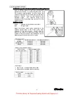
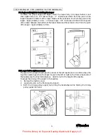
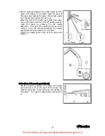
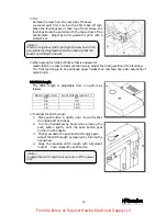
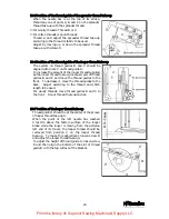
5-7 Changing the amount of the looper font-to-back movement 

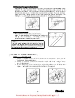
The clearance between the point of the left needle 
and the back side of the looper when the looper 
moves to the right from the extreme left end of its 
travel should be 0.05~0.1mm. 
The clearance between the point of the right needle 
and the back side of the looper should be 0.2~0.3mm.   
The amount of the looper front-to-back movement is 
factory-set properly for needle counts 9~11. 
If you use needle counts 12~14, adjust the amount 
as required (see below). 
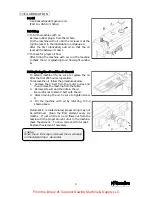
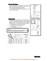
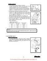
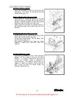
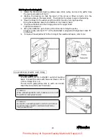
1.


Remove rear bed cover A. 

2.


Loosen the nut on the looper front-to-back rod 
pin. 

To decrease the amount, move the rod pin to X. 
To increase the amount, move the rod pin to Y. 
The amount range is from 2.3 to 3.1mm. 
The amount is factory-set at 2.7 to 2.8mm. 
Adjust according to the needle count. 
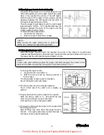
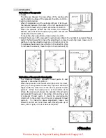
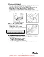
If the amount is excessively decreased, the needle 
will rub against the back of the looper, causing 
needle breakage.  If the amount is excessively 
increased, the clearance between the needle and the 
back of the looper will increase and then skip 
stitching may occur when the looper moves to the 
left. 


6

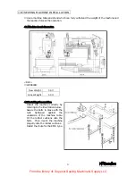
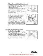
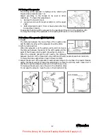
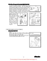
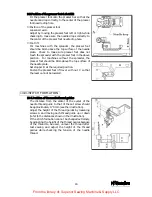
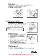
FRONT AND REAR NEEDLE GUARDS   

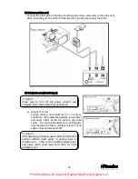
6-1 Position of the needle guard (rear) 

Align line (a) on needle guard (rear) A with the 
center of the right needle hole when the needle 
guard (rear) is at the bottom of the stroke. 
When point of the looper passes the back side of the 
needles, the needle guard (rear) should push the 
right needle slightly toward the front and the 
clearance between the point of the looper and the 
left needle should be approximately 0.2mm. 


From the library of: Superior Sewing Machine & Supply LLC

Summary of Contents for LX5801

Page 1: ...INSTRUCTION Industrial Sewing Machines First published August 1991 Third edition August 2004 No 040037 WX8800 WX8700 LX5801 WX8842 WX8842 1 MC30 From the library of Superior Sewing Machine Supply LLC ...

Page 2: ...adjusting cleaning threading the machine or replacing the needle be sure to turn off the power 4 Never start the machine with no oil in the reservoir 5 Refer to the parts list as well as this instruction manual before maintenance If the machine includes a thread trimmer read and study the instruction manual for the thread trimmer carefully 6 The contents described in this instruction manual are su...

Page 3: ...Position of the presser foot foot lift 16 10 STITCH FORMATION 10 1 Position of the needle thread guides 16 10 2 Position of the thread guide on the needle thread take up 17 10 3 Timing of the needle thread take up 17 10 4 Position of the needle thread guard 17 10 5 Position of the thread guide of the spreader thread take up 18 10 6 Position of the thread guide of the looper thread take up 18 10 7 ...

Page 4: ...edle check the needle carefully to see that the scarf is turned to the rear of the machine see the illustration Then install the needle correctly 1 3 Threading the machine Thread the machine correctly by referring to the illustration below Threading the machine incorrectly may cause skip stitching thread breakage and or uneven stitch formation Thread tension should be changed according to various ...

Page 5: ...he machine speed refer to the motor pulley outer diameter on the table below Adjust where to position the motor by pressing the finger onto the middle of the belt so that 1 2cm deflection can be obtained see the illustration on the right Machine speed TYPE MAXIMUM SPEED STANDARD SPEED WX8803 6000SPM 5500SPM WX8803EMK 5000SPM 4500SPM LX5801 6500SPM 6000SPM Motor pulley selection table Machine speed...

Page 6: ... the oil and the oil element To extend machine life be sure to replace the oil after the first 250 hours of operation To replace the oil follow the procedures below 1 Remove the V belt from the motor pulley and then remove the machine from the table 2 Remove screw D and then drain the oil Be careful not to stain V belt with the oil 3 After draining the oil be sure to tighten screw D 4 Fill the mac...

Page 7: ...eight 56 Gross Weight 59 4 2 Installing the machine Install the machine correctly by referring to the illustration below Secure the bolts in place with the nuts tightened against the underside of the machine table Fit the rubber cushions onto the bolts Then mount the machine properly onto the rubber cushions Install the chute for the EMK type From the library of Superior Sewing Machine Supply LLC ...

Page 8: ... j 75 0 I G I 6 _j lJl 3 9 9 I o DEPTH4 12 26 DEPTH OF THE COUNTERSUNK HOLE 4 18 r 1 lj _ l f I H m I I 9 _ 1 1 1 1 DEPTH OF THE COUNTERSUNK HOLE4 w 0 Jl s e Q I 25 I I 561 I I I 1 70 ww I I J CD J w 85 120 _j D D lJ1 I 55 I 427 lA V fo s D k 377 J D t v t 0 w V 6 J J1 V lL 1 6 2 98 5 D 0 f s _ 0 D J 32 3 5 lJ1 lJl J1 lJl A 5 53 581 656 746 J 0 0 1 rl From the library of Superior Sewing Machine Su...

Page 9: ...ooper blade and the extension line from the point of the looper Approximately 1 2mm 5 2 Looper left to right movement The point of the looper should pass the center of the left needle and 1 3 1 6mm above the top of its needle s eye when the looper moves to the left or right on the front or back side of the needles see the illustration below Refer to 5 4 for the height of the needle To adjust the t...

Page 10: ...p of the left needle s eye on the back side of the needle when the point of the looper has reached the center of the left needle with the machine pulley turning in the operating direction see 5 2 To adjust the height of the needle 1 Set the needle bar at the top of its stroke 2 Remove the plug on the head cover 3 Loosen screw A 4 Move the needle bar up or down Needle height Bmm LOOPER SETTING DIST...

Page 11: ...edle is approximately 0 2mm To change the looper s orbit 1 Loosen screw B on eccentric A 2 Shift the timing mark by moving eccentric A front or back The timing mark is factory set for standard Do not change the orbit extremely The timing mark is at the standard position The 3 o clock end of the orbit is at a slightly up position To advance the timing of the looper to the needle Shift the timing ma...

Page 12: ...nge is from 2 3 to 3 1mm The amount is factory set at 2 7 to 2 8mm Adjust according to the needle count If the amount is excessively decreased the needle will rub against the back of the looper causing needle breakage If the amount is excessively increased the clearance between the needle and the back of the looper will increase and then skip stitching may occur when the looper moves to the left 6...

Page 13: ... looper by pressing the left needle backward Then turn the needle guard rear with screw B to set the clearance between the needle guard rear and the needle at 0 1 0 15mm Adjust the needle guard rear front to back with screw C 6 2 Position of the needle guard front Set the clearance between the needles and needle guard front A when the point of the looper has reached the center of the right and lef...

Page 14: ... the adjusting lever pin in direction a or b To decrease the amount move the pin in the direction of a To increase the amount move the pin in the direction of b 7 2 Position of the spreader thread guide The clearance between spreader thread guide B and spreader A should be 0 5 0 8mm When the spreader is at the extreme right end of its travel point a of the spreader thread carrying notch should be ...

Page 15: ...te and the bottom surface of the spreader should be 8mm Left to right position When the spreader is at the extreme left end of its travel the distance between the center of the left needle and the point of the thread carrying notch should be 4 5 5 5mm When the spreader passes the left needle the distance between the point of the thread carrying notch and the left needle should be 0 5 0 8mm To make...

Page 16: ...e C should be 1mm and the eyelet of spreader thread guide C should be approximately 0 5mm left to the center line of the slot of spreader thread guide B To make the above adjustment loosen two screws D and screw E and move each thread guide up or down left or right or front or back as required 8 FEED DOGS STITCH LENGTH 8 1 Feed dog height tilt Height When the feed dogs are at the top of their stro...

Page 17: ... 1 4 4 2mm as follows Stitch length mm No of stitches within 1 4 2 6 0 3 6 7 0 2 4 10 5 1 4 18 0 To adjust the stitch length 1 Press push button A lightly until its end touches the inside part and clicks 2 Turn the handwheel by hand while pressing the push button lightly until the push button goes further into the depth 3 Then press down the push button strongly again Adjust the stitch length as r...

Page 18: ... and lower limits with two stoppers D To adjust the differential feed ratio during sewing move lever B up or down within this range and then set lever B at the required position The differential feed ratio varies according to the stitch length See the table below Differential feed ratio Stitch length mm Max normal diff feed Max reverse diff feed 3 6 1 1 2 1 0 7 2 5 1 1 6 1 0 7 2 0 1 1 8 1 0 7 1 4 ...

Page 19: ...hould be 8mm above the top surface of the needle plate Set stopper B at the required position Fasten the presser foot lift lever with nut C so that the lever cannot be lowered 10 STITCH FORMATION 10 1 Position of the needle thread guides The distance from the center of the eyelet of the needle thread guide to that of the set screw should be approximately 17 5mm see the illustration Adjust the heig...

Page 20: ...its stroke the center of the eyelet of thread guide A should be level with the top surface of needle thread guard B In addition A should be parallel with B To adjust the height of needle thread guard B loosen screw C and move needle thread guard B up or down To tighten the needle thread move up B To loosen the needle thread move down B For cotton threads non stretchable threads Bring the needle th...

Page 21: ...es B and C and move the thread guides to the front To decrease it move the thread guides to the back Adjust according to the thread and stitch length to be used For woolly threads move thread guides B and C to the front Do not thread the tension disk 10 7 Position of the looper thread take up Thread guide D should be at the center of the groove of looper thread take up A When the point of the left...

Page 22: ... the front of the presser foot Adjust the front of the presser foot according to the type of fabric and or elastic to be used To sew heavy weight elastic onto the fabric raise the front of the presser foot This reduces resistance and feeds the fabric smoothly Loosen nut D and turn screw E as required 11 4 To install the tape guide Install tape guide shaft A as close to the needle as possible but t...

Page 23: ...lastic feed small roller To adjust the pressure of small roller A loosen adjusting nut B as required To increase the pressure turn clockwise To decrease the pressure turn counterclockwise Adjust the pressure according to the elastic to be used 11 7 Checking the performance of the elastic feeder If the elastic feeder does not work well it will not feed elastic uniformly causing various kinds of tro...

Page 24: ...r Move the shaft to the right to provide clearance up and down 2 Tighten screw C on the right collar temporarily 3 Loosen screw D Remove lower knife E downward 4 Align the blade of new lower knife E with the top surface of the needle plate Tighten screw D 5 The upper and lower knives are overlapped by loosening screw C on the collar 6 Place a thread between the knives and check for the proper cutt...

Page 25: ... the knives become dull sharpen the lower knife first see the illustration If cutting is still not performed properly replace the upper knife 13 REPLACING THE TIMING BELT 13 1 To remove the timing belt 1 Loosen the eight arm cover set screws and the six oil reservoir set screws see the illustration Remove each part 2 Loosen two screws A Remove the handwheel to the right while turning it slowly see...

Page 26: ...extreme right end of its travel by turning the pulley Bring the needle bar down to the bottom of its stroke by hand 4 Then place the belt onto the timing pulley on the upper shaft Tighten two screws A 5 Bring the needle bar up to the top of its stroke by turning the pulley Check to make sure mark P on the handwheel is aligned with alignment mark O on the bed 6 To make a fine adjustment for the tim...

Page 27: ...rd Connect the cords with referring to the following picture also refer to the parts list After connecting fix the cords with bands to the proper place under the table 14 3 Adjustment Electric type a Height of Cutter Loosen screw E and adjust lever F in order to set 24 mm of the distance between lower cutter and upper cutter at the top position top dead point During this adjustment do not forget t...

Page 28: ...rlap properly between upper cutter and lower cutter c Power of Upper Cutter After loosen screw I then adjust the pressurized power of upper cutter against lower cutter by screw J 14 4 Air piping wiring Air type Connect the air tube and the electric cords with referring to the following picture also refer to the parts list After connecting fix the air tube and the electric cords with bands onto the...

Page 29: ... before adjusting cleaning etc 14 5 Air pressure Set the air pressure at 4 5 kg cm2 by regulator Do not increase the air pressure over 5kg cm2 which may cause trouble 14 6 Adjustment Air type a Height of Cutter Loosen screw K and adjust lever L in order to set 24 mm of the distance between lower cutter and upper cutter at the top position top dead point b Overlapping of Cutter 1 Loosen screw M the...

Page 30: ...27 15 CLEANING THE MACHINE At the end of each day remove the needle plate and clean the slots of the needle plate and the area around the feed dogs From the library of Superior Sewing Machine Supply LLC ...

Reviews: