background image

From the library of: Superior Sewing Machine & Supply LLC

Summary of Contents for wx-8800 series

Page 1: ...Industrial Sewing Machines WX 8800 SERIES TECHNICAL INSTRUCTION MANUAL fj MORIMOTO MFG CO LTD From the library of Superior Sewing Machine Supply LLC ...

Page 2: ...sition of the rear needle guard 2 2 Position of the front needle guard 3 The Top Cover Looper 8 3 1 Position of the top cover looper 3 2 Position of the top cover thread guide 3 3 Top cover looper timing 4 Feed Dogs and Stitch Length 12 4 1 Feed dog height and level 4 2 Adjustment of the stitch length 4 3 Adjustment of the differential feeding 5 Presser Foot Adjustments 15 5 1 Position of the foot...

Page 3: ... up and take up eyelet 19 6 7 Position of the looper thread take up eyelets 6 8 Looper thread take up cam 21 6 9 Height of the guide plate 7 The Timing Belt 22 7 1 Timing belt markings 7 2 Changing the timing belt 8 Lubrication System 25 8 1 Placing the oil in the machine 8 2 Oil flow rate 9 The Tabletop 26 9 1 Tabletop cutout design specification 26 9 2 Mounting the machine From the library of Su...

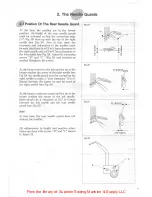
Page 4: ... the looper is set into the top of the looper carrier A Fig 1 and fastened in place with the set screw B Fig 1 The height and the position of the looper are automatically set as long as the looper is set fully into the looper carrier and the set screw is tightened squarely onto the flat on the looper shaft By design the inner surface of the looper is offset three degrees away from the horizontal p...

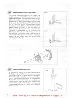
Page 5: ... 3B Adjustment of the looper needle timing is done by removing the top housing cover loosening the set screwsCA on the top timing pulley and moving the position of the timing pulley on the top shaft accordingly see Fig 4 Looper Needle Distance At the time the needles are in their lowest position the looper is in its rightmost position At this time the distance from the tip of the looper to the cen...

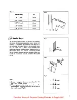
Page 6: ...the needle must be 1 to 1 5mm Fig 7 If the needle height needs adjusting remove the face plate to gain access to the clamp screw A Fig 8 Loosen the clamp screw by using A 3mm hex key wrench Adjust the height up or down as needed Retighten the clamp screw Note 1 Do not overtighten the screw more than 3 to 4 ft lbs 30 to 35 kgcm torque 2 When tightening the clamp screw be sure the needles are in ali...

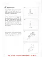
Page 7: ... both two and three needle models see Fig 10 and 11 To make an adjustment first check to see that the needles are in proper alignment with the needle holes in the needle plate Fig 9 Next check to be sure the looper is set so that the set screw is positioned squarely on the flat of the looper shaft see Fig 1 Next check to be sure that the looper avoid angle is appropriate see section 1 6 Three Need...

Page 8: ...oosen the set screw B Fig 13 on the avoid eccentric A Fig 13 and move the eccentric forward or backward on the shaft as needed Moving the timing mark forward in the X direction Fig 14 decreases the avoid angle Moving the timing mark backward in the Y direction Fig 14 increases the avoid angle Standard looper avoid angle is achieved when the timing marks are aligned Caution The adjustment of the lo...

Page 9: ... looper by turning the screw A Fig 17 By turning the screw clockwise the assembly will move in the X direction see Fig 18 This will decrease the looper avoid motion By turning the screw counterclockwise the assembly will move in the Y direction This will increase the looper avoid motion The standard amount of looper avoid motion should be 2 3 to 3 1mm By decreasing the looper avoid motion needle b...

Page 10: ... As the looper moves to the left and the tip of the looper reaches the center of the right needle see Fig 20 the needle guard must be contacting the right needle to make a zero clearance 0 to 0 05mm between the looper tip and the scarf of the right needle see Fig 20 As the looper continues across and the tip of the looper reaches the center of the left needle there should be a clearance of 0 15 to...

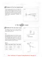
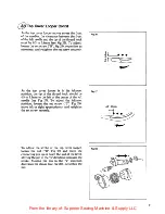
Page 11: ...ition Of The Top Cover Looper The height of the top cover looper should be 9 0 to 11 0mm above the top surface of the needle plate see Fig 24 Recommended height for the top cover looper for gauge sizes 1 8 5 32 and 3 16 is 9 0mm Recommended height for gauge sizes 7 32 and 1 4 is 11 0mm see chart 2 To adjust the height of the top cover looper loosen the clamp screw B Fig 25 and position up or down ...

Page 12: ...he thread hook should be 4 5 to 5 5mm to the left of the center of the left needle see Fig 27 To adjust the leftmost position loosen the set screw C Fig 25 move left or right appropriately and retighten the set screw securely To adjust the stroke of the top cover looper loosen the nut D Fig 28 and move the connecting pin up or down the slot of the lever Moving the pin in the b direction increases ...

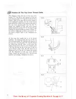
Page 13: ...d to adjust up or down and screws B are used to adjust right or left Retighten the screws At the time the needle bar is in its lowest position the distance from the top of the top cover thread guide D Fig 29 to the bottom of the top cover thread eyelet B Fig 29 should be 1 0mm see Fig 29 Also at that time the center of the hole in the top cover thread eyelet B Fig 32 and the tip of the slot in the...

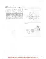
Page 14: ...ne loosen the set screws A Fig 33 on the top cover eccentric and move forward or backward as nesessary Moving the timing mark in the direction of E see Fig 34 will increase the speed of the timing Moving the timing mark in the direction of F will decrease the speed of the timing of the top cover looper Retighten the set screws Fig 33 Fig 34 From the library of Superior Sewing Machine Supply LLC ...

Page 15: ...ately To adjust the height of the front and rear feeders loosen the screw at the base of each feeder see Fig 36 and move up or down to the proper height Retighten the screws The feeders must also be level to the surface of the needle plate To adjust the level of the feeders remove the back cover on the bed of the machine Loosen the set screw D Fig 37 with a 2 5mm hex key wrench access to the screw...

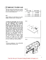
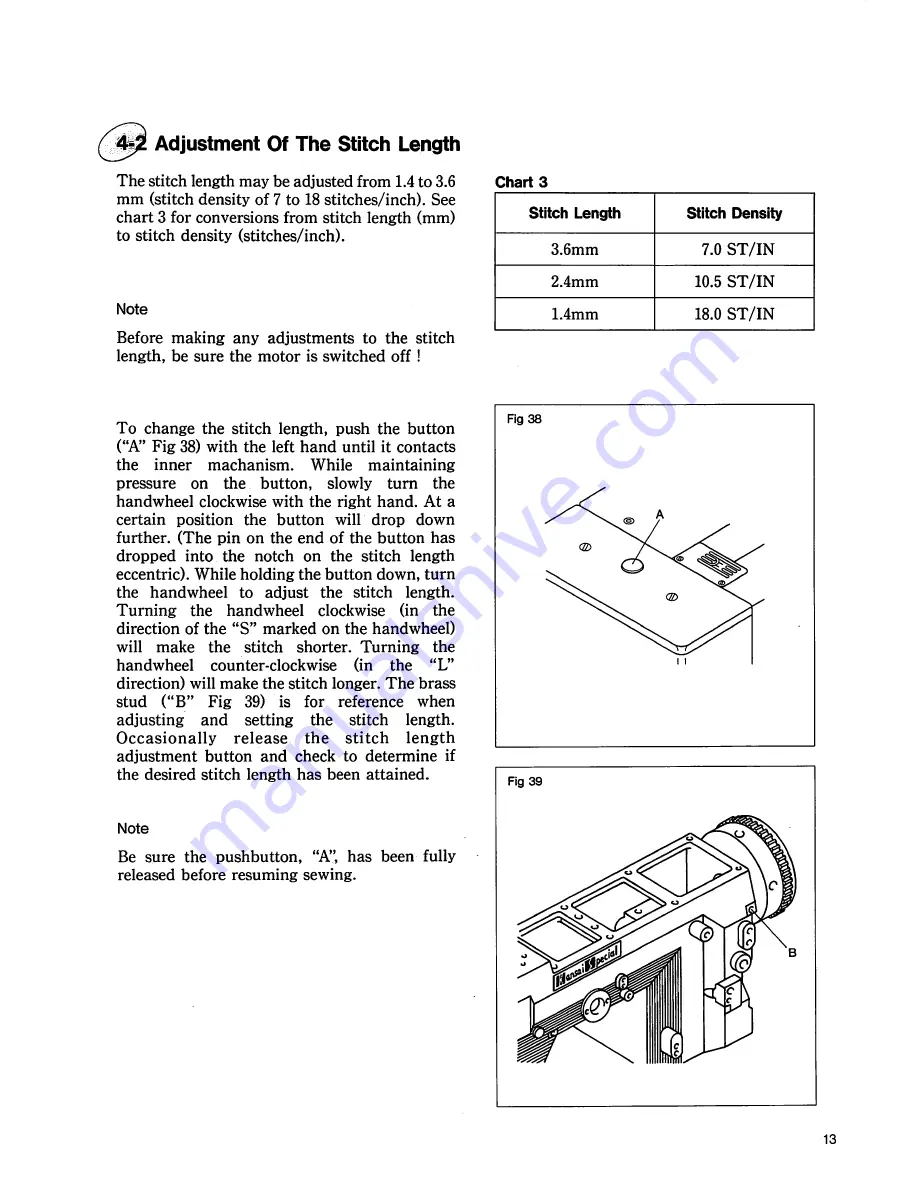
Page 16: ... the button has dropped into the notch on the stitch length eccentric While holding the button down turn the handwheel to adjust the stitch length Turning the handwheel clockwise in the direction of the S marked on the handwheel will make the stitch shorter Turning the handwheel counter clockwise in the L direction will make the stitch longer The brass stud B Fig 39 is for reference when adjusting...

Page 17: ...ased to a minimum of 1 0 7 Retighten the hand nut A It is possible to vary the differential feed ratio during the sewing operation To do this connect a chain fastened to a foot pedal to the front of the lever point E Fig 40 Next loosen the hand nut A Then set the differential range maximum up and down positions of the lever with the stoppers D Fig 41 For this type of operation do not retighten the...

Page 18: ... of the presser foot When the presser is at full lift height it should never exert any pressure against the top looper that may distort its shape Machines without a top cover looper may have a presser foot lift height of up to 8mm To limit the presser lift height there is a stop screw B Fig 44 positioned below the lifter lever on the back of the machine Loosen the lock nut C Fig 44 and position th...

Page 19: ... be horizontal To adjust place the needle bar at its lowest position loosen the clamp screw D Fig 46 and position appropriately to level Retighten the clamp screw The distance from the eyelets to the first screw B Fig 46 should be 55mm as shown in Fig 46 To adjust the distance loosen screws B and C and move the take up eyelet to the right or left as necessary By increasing the distance moving the ...

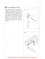
Page 20: ... is such that the top surface of the wire is in line with the center of the holes in the needle bar eyelet A Fig 48 when the needle bar is at its lowest position Height adjustments to the take up wire may be made to accommodate the different characteristics of the various threads used If a slick stretchy type of thread such as texturized polyester or nylon is used the position of the take up wire ...

Page 21: ...ads Also this is the position used for general sewing appli cations such as sewing medium to heavy weight knits double knits or woven materials If slick stretchy types of thread such as texturized polyester or nylon is used or for sewing thin light materials the thread nipper should be placed on the stand off located on the lower front face of the machine head as shown in Figure 50 From the librar...

Page 22: ...the bottom of the slot Retighten the screws Notes For Threading If a small stitch length narrow needle gauge and standard thread such as cotton or wrapped thread is used pass the cover thread through either of the holes C or D see Fig 51 and pass the thread in front of the take up A Fig 51 If a long stitch length wide needle gauge and stretchy thread such as texturized polyester or nylon is used p...

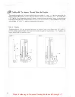
Page 23: ... fed into the stitch loosen the screws and move the eyelets B and C forward To decrease the amount of looper thread fed into the stitch move eyelets B and C backward Retighten the screws Note On Threading If stretchy thread such as texturized polyester or nylon is used move the eyelets B and C forward as far as possible and don t pass the thread through the small tension A Fig 54 on the looper thr...

Page 24: ...56 To adjust the position of the take up cam at this time loosen the set screws A Fig 56 and move the take up cam forward or backward as necessary Retighten the set screws securely Height Of The Guide Plate The distance from the top surface of the support plate to the bottom of the guide plate should be 4 to 5mm as shown in Fig 56 To adjust loosen the screw C Fig 56 and move the guide plate up or ...

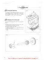
Page 25: ... is the largest 7 Changing The Timing Belt To remove the timing belt follow the procedures below 1 Remove all the screws from the top cover plate and the oil pan as shown in Fig 57 2 Remove the top cover plate 3 Loosen the set screws A Fig 58 from the upper shaft union 4 slowly turn and pull the handwheel out to the 7 The Timii Belt From the library of Superior Sewing Machine Supply LLC ...

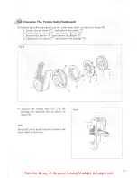
Page 26: ...y I b Loosen the set screws H and remove the fan G c Remove the screws F and remove the flange E d Loosen the set screws C and remove the bearing D 6 Remove the timing belt K Fig 60 through the machine bed as shown in figure 60 Be careful not to apply torque or stress to the lower shaft at this time i i From the library of Superior Sewing Machine Supply LLC ...

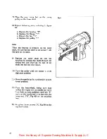
Page 27: ...chine by passing the shaft through the timing belt and inserting the end of the shaft into the top shaft union 10 Turn the pulley until the looper is in its rightmost position 11 Move the needle bar by hand until it is in its lowest position 12 Turn the handwheel being sure that neither the looper nor the needle bar move from their extreme positions until the P mark on the handwheel is in line wit...

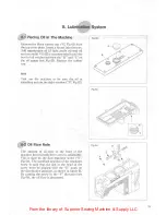
Page 28: ...hine to be sure the oil is splashing up into the sight window B Fig 62 Oil Flow Rate The amount of oil flow to the front of the machine head needle drive area is adjustable This is done by the flow regulator screw E Fig 64 The standard position of the regulator screw is such that the slot in the head of the screw must be aligned with the D mark on the distribution junction as shown in figure 64 By...

Page 29: ...25 1 53 5 50 4 12mm Dia Holes 26mm Dia 3 C Bore 4mm Deep From the library of Superior Sewing Machine Supply LLC ...

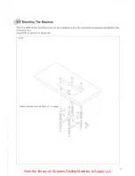
Page 30: ...8800 Series machines may be top mounted using the mounting equipment supplied in the accessory box Assemble as shown in figure 66 Fig 66 Table thickness must be 40mm or Inches From the library of Superior Sewing Machine Supply LLC ...

Page 31: ... 201 460 1633 MORIMOTO MFG H K LTD 203 207 G F Lai Chi Kok Road Sham Shui Po Kowloon Hong Kong Tel 3 918357 9 Telex 31167 MORHK MX Fax 3 7891707 MORIMOTO MFG H K LTD SINGAPORE REP OFFICE 1 Marine Parade Central 10 01 Parkway Builders Centre Singapore 1544 Tel 3457576 Telex RS25138 A B MMSPL Fax 3449603 KANSAI SPECIAL EUROPE G M B H Wahler Strasse 37 4000 Dusseldorf 30 GERMANY Tel 0211 658020 Telex...

Reviews: