Page 19 of 23
DWG ID: 181-0104-00
Date: 2006-01-24
You may of course run the wires to where ever you can find the appropriate power
sources. The fuse box is recommended due to its close proximity to the most common
equipment mounting locations.
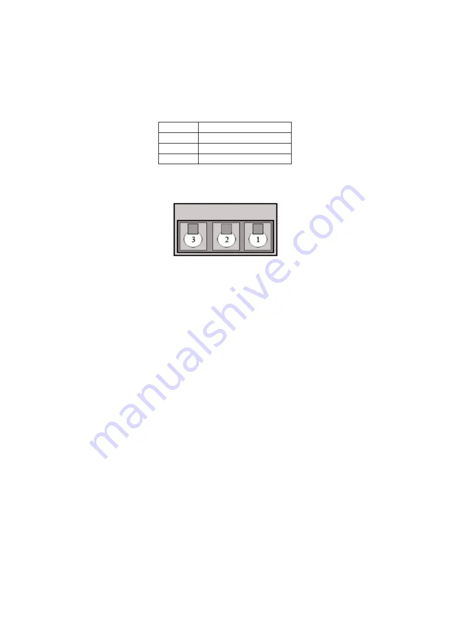
Terminal
Connection
1
Vehicle Ground
2
+12 V dc (ignition sense)
3
+12 V dc constant
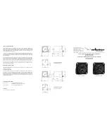
Figure 3-1
:
Power plug pin assignment
Figure 3-2
:
Power connector view from rear.
With power applied the LED indicators will begin their sequence which I will cover in
the next section.
Make sure the GPS antenna is hooked up and mounted somewhere either in or outside the
vehicle with a clear view of the sky.
The GPS antenna is magnetic and will hold to the body of the vehicle. It is recommended
that this antenna be mounted on the roof of the vehicle. This is because the antenna sent
with the KML is called a “Ground-Plane” antenna. This means the vehicle body becomes
the ground-plane of the antenna. This type of antenna may be used from inside the
vehicle but the efficiency will be significantly less.
You must use the antenna provided to receive GPS data. Another type of antenna, such as
a “whip”, wired up to the GPS antenna will receive very little if any satellite signals.
There are 2 reasons for this:
1.
The actual “node” that is the antenna has a small preamp built into it
2.
GPS signals are “circularly polarized” and as such the antenna is built specifically
to accommodate this type of polarization.


