15
B
A
a1
b2
x
b1
x
x
0.5 m
B
A
a1
b1
x
x
180°
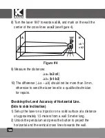
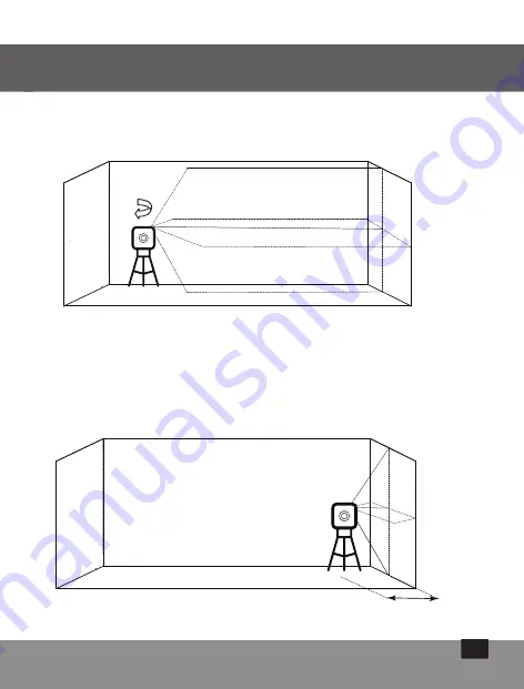
5) Turn the laser 180° towards wall
B
, and mark on the wall
the center of the cross lines as
b1
(see figure 2).
6) Move the laser level towards wall
B
and position it
approximately 0.5 meter from wall
B
.
7) Mark on wall
B
the center of the cross lines as
b2
(see figure 3).
Figure # 2
Figure # 3
Summary of Contents for Prolaser 852G
Page 1: ...User Manual Manual del usuario Manuel d utilisation Prolaser Cross Line Laser Model No 852G...
Page 62: ...62 Kapro 852G Prolaser Cross Line Laser 852G Prolaser Cross Line Laser GREEN RU...
Page 63: ...63 64 65 66 67 68 69 70 72 73 74 79 80 81...
Page 64: ...64 40 130 1 4...
Page 65: ...65 II EN 60825 1 25249 6 65...
Page 66: ...66 10 C 45 C...
Page 67: ...67 1 2 3 3 1 2 3 4 5 USB Type C...
Page 68: ...68 1 2 3 4 5 6 7...
Page 69: ...69 1 2 a b c 3 4 5...
Page 70: ...70 3 1 2 1 ON 3 H V 4 3 5 1 OFF...
Page 71: ...71 1 M 2 H V 3 4 M 5 1...
Page 72: ...72 40 1 2 P 3 4 P...
Page 73: ...73...
Page 74: ...74 B A a1 0 5 m x Kapro 1 5 2 0 5 3 4 a1 1 5 0 5 1...
Page 75: ...75 B A a1 b2 x b1 x x 0 5 m B A a1 b1 x x 180 5 180 B b1 2 6 0 5 B 7 b2 3 2 3 0 5...
Page 76: ...76 8 180 2 4 9 a a2 a1 b b1 b2 10 a b 3 1 1 5 5 2 4 B A a1 b1 x b2 x x a2x 180...
Page 77: ...77 1 5 m a1 x 3 a1 5 4 a1 2 6 1 5 5 5 6 x a1 x a2...
Page 78: ...78 5 a1 a2 1 5 1 4 2 a1 7 3 2 4 5 7 4 a1 x...
Page 79: ...79 2 m a1 a2 x x x 6 2 a1 8 7 a1 a2 1 5 2 8...
Page 82: ...82...
Page 83: ...83...


