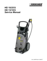
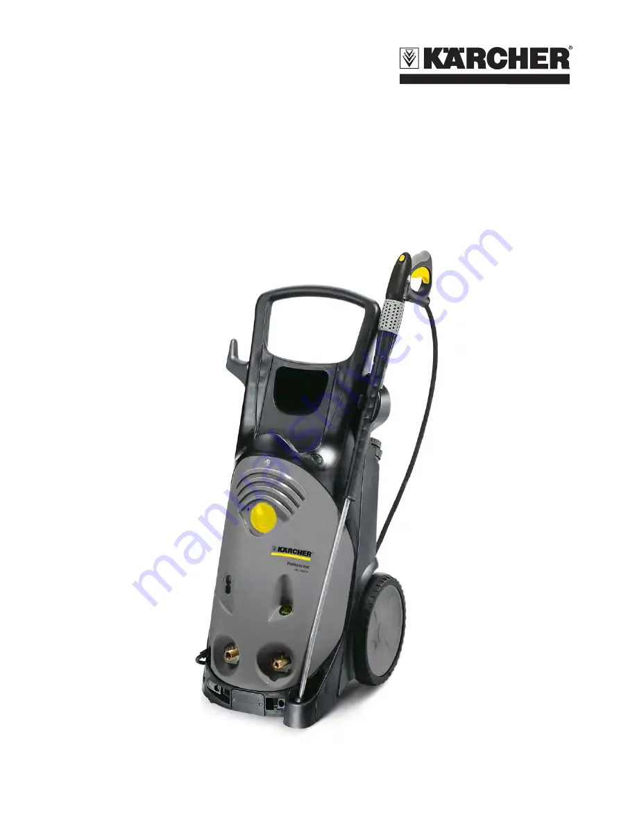
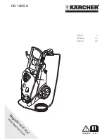
Kärcher HD 10/25 S VEX, Service Manual
The Kärcher HD 10/25 S VEX is a powerful pressure washer designed for heavy-duty cleaning tasks. Make sure you have the Operating Manual for this product to ensure proper use. Download the manual for free from 88.208.23.73:8080 and get the most out of your machine.
Share
Download

Reviews:
No comments
Related manuals for HD 10/25 S VEX
HS-3000
Brand: Landa Pages: 28
CALIFORNIA
Brand: Lavorwash Pages: 104
BVE Series
Brand: Ramteq Pages: 20
T 350
Brand: Kärcher Pages: 8
210
Brand: Kärcher Pages: 36
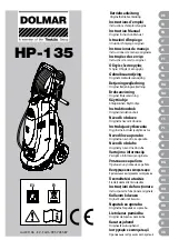
DOLMAR HP-135
Brand: Makita Pages: 113
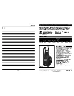
PW1380
Brand: Campbell Hausfeld Pages: 13
PW1750
Brand: Campbell Hausfeld Pages: 18
PW2120
Brand: Campbell Hausfeld Pages: 8
PWE-1800
Brand: Echo Pages: 20
PHW
Brand: Landa Pages: 26
POWER
Brand: Lavor Pages: 20
HD 10/25 S VEX
Brand: Kärcher Pages: 44
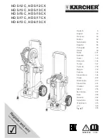
HD 5/12 C
Brand: Kärcher Pages: 20
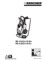
HD 4.5/32-4 S Eb HD 4.5/32-4 S Ec
Brand: Kärcher Pages: 36
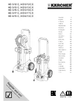
HD 5/12 C
Brand: Kärcher Pages: 65
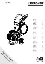
G 4.10 M
Brand: Kärcher Pages: 208
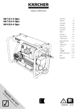
HD 7/11-4 Cage
Brand: Kärcher Pages: 196


