-
3
–
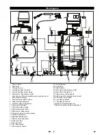
The safety valve protects the high pressure system against
excessive pressure.
–
This valve is set and sealed in the factory. Do not change the
setting.
When the water supply is scarce, the flow switch switches off the
burner.
–
When the water supply is scarce, the flow switch switches off
the burner.
–
Accomodates the switching head during spray jet operations.
–
The flow switch (additional switching head) prevents the burn-
er stage 2 from being switched on during spray jet operations
(approx. 1500 l/h) in order to avoid overheating.
–
The burner stage 1 is released when there is function failure.
The safety temperature limiter switches off the burner when the
maximum permissible steam pressure is exceeded.
–
The safety valve "steam stage" protects the installation
against excessive pressure in the steam stage.
–
This valve is set and sealed in the factory. Do not change the
setting.
The exhaust temperature limiter switches off the burner when the
maximum permissible exhaust temperature is exceeded.
–
When there is a pressure shortfall (1.2 MPa), the pressure
guard switches the operating mode "Operate with steam"
over to "Operate using hot water".
–
The operating mode "Operate with steam" is released only
when the minimum pressure (1.4 MPa) is reached.
–
A main switch that can be locked is to be installed at a safe
and easily accessible place to switch off the entire heating
unit.
–
The main switch is to be switched off while carrying out any
repairs or maintenance jobs.
If a pump module other than the HD 4000 E is used, you must
check if this module has a pressure limit (max. 1.4 MPa). If this is
not the case, you must install an additional safety valve (order no.
6.412-271) at the input.
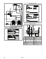
Safety Devices
Safety valve
Safety switch for water scarcity
Water shortage safeguard
Switch head for spray jet operation (with upgrade kit
spray jet only)
Safety temperature limiter (upgrade kit for steam
stage only)
Safety valve "steam stage" (upgrade kit for steam
stage only)
Temperature stop for exhaust gases
Pressure monitor (upgrade kit for steam stage only)
Main switch
Pump module
28
EN
Summary of Contents for HWE 4000
Page 2: ...2 ...
Page 12: ... 10 Maßblatt c Brennkammer ausziehen d Kesselmantel abnehmen 12 DE ...
Page 35: ... 10 Specifications sheet C Pull out the burner chamber d Remove the boiler sleeve 35 EN ...
Page 59: ... 11 Feuille de mesure c Sortir la chambre de brûleur d Enlever le manteau de chaudière 59 FR ...
Page 107: ... 10 Måttblad c Dra ut brännkammare d Ta av behållarens mantel 107 SV ...
Page 131: ... 11 Φύλλο διαστάσεων c Εξαγωγή θαλάμου καύσης d Αφαίρεση μανδύα λέβητα 131 EL ...
Page 155: ... 10 Méret lap c Égéskamrát kihúzni d Kazánburkolatot levenni 155 HU ...
Page 178: ... 10 Přehled rozměrů c Vytažení spalovací komory d Sejmutí pláště kotle 178 CS ...
Page 202: ... 11 Arkusz z wymiarami c Wyjąć komorę spalania d Zdemontować płaszcz kotła 202 PL ...
Page 226: ... 11 Информационный листок с Извлечь топку d Снять обшивку котла 226 RU ...
Page 241: ......


