-
6
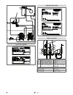
A Operating field
B Thermostat "hot water"
C Temperature regulator "steam stage" (upgrade kit for steam
stage only)
Press the key for releasing the burner fault.
Note:
The info mode can be called up only during the operating
mode in each state of the burner.
Press the key for approx. 0.5 seconds.
You will see a display with an info number and a value dis-
played after it.
Example: Consumed fuel = 1772 l/m
3
The system goes back to displaying the operating status after info
number 10 or if there is a waiting period of 20 seconds.
To go to the next information:
Press the key for approx. 0.2 seconds.
Note:
The service mode may only be accessed by Customer
Service.
1 Emergency-stop button
2 Temperature
2a cold
2b hot
3 Fault
1 Emergency-stop button
2 Operating mode
2a Water operations
2b Steam operations
3 Temperature
3a cold
3b hot
–
For connection values, see technical data and type plate.
–
The electrical connections must be done by an electrician ac-
cording to IEC 60364-1.
Check high pressure hose, pipe connections, fittings and wa-
ter jet for damage every time before use.
Check hose coupling to ensure that it sits firmly and is leak-
proof.
Press the factory-recommended main switch for emergency
stop of the main plant or the emergency stop switch of the en-
try to the heating room.
Control elements
Operating field
Unlocking burner faults
Info mode
Info No.
Displayed value
0
Consumed fuel (captured via the input of the im-
pulse counter)
1
Operating hours Stage 1
2
Operating hours Stage 2
3
Number of burner starts that have been carried
out
4
Software no. of the firing manager
5
Creation date of the software
6
Appliance no.:
–weishaupt–
l/m
3
7
Appliance testing date
8
Current eBUS address
9
Oil monitoring function
10
Current eBUS address of regulator
Service mode
Remote control (optional)
(A) Remote control without steam operations
(B) Remote control with steam operations
Start up
Power connection
Operation
Making the plant ready for operations
Switch-off in case of emergency
Not-
A
us
Temp.
kalt heiß
Störung
Not-
A
us
B
etrieb
Wasser Dampf
Temp.
kalt heiß
1
2
3
A
B
2
a
2
b
1
2
3
2
a
2
b
3a
3b
31
EN
Summary of Contents for HWE 4000
Page 2: ...2 ...
Page 12: ... 10 Maßblatt c Brennkammer ausziehen d Kesselmantel abnehmen 12 DE ...
Page 35: ... 10 Specifications sheet C Pull out the burner chamber d Remove the boiler sleeve 35 EN ...
Page 59: ... 11 Feuille de mesure c Sortir la chambre de brûleur d Enlever le manteau de chaudière 59 FR ...
Page 107: ... 10 Måttblad c Dra ut brännkammare d Ta av behållarens mantel 107 SV ...
Page 131: ... 11 Φύλλο διαστάσεων c Εξαγωγή θαλάμου καύσης d Αφαίρεση μανδύα λέβητα 131 EL ...
Page 155: ... 10 Méret lap c Égéskamrát kihúzni d Kazánburkolatot levenni 155 HU ...
Page 178: ... 10 Přehled rozměrů c Vytažení spalovací komory d Sejmutí pláště kotle 178 CS ...
Page 202: ... 11 Arkusz z wymiarami c Wyjąć komorę spalania d Zdemontować płaszcz kotła 202 PL ...
Page 226: ... 11 Информационный листок с Извлечь топку d Снять обшивку котла 226 RU ...
Page 241: ......


