35
ICC 1 S D
Basic Settings and Service Procedures
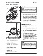
Adjusting vacuum intake
–
Lower vacuum intake.
–
Loosen clamp bolts (3) on both sides.
–
Loosen lock nuts (5) on both sides.
–
Using adjustment screws (4), adjust vacuum
intake in such a way that the front sealing lip
(2) at the coarse dirt flap (1) has about 0 to 1
mm ground clearance.
–
Using guide rods (7), adjust sealing lip (2) to
provide about 10 to 18 mm ground clearance
at rear.
–
After each adjustment, again check the other
measurements.
Sweeping Mechanism – Vacuum intake
1
Coarse dirt flap
2
Sealing lip
3
Caster adjusting clamp bolt (4x)
4
Adjusting screw
5
Lock nut
6
Support caster, vacuum intake
7
Adjusting guide rods (2x)
Summary of Contents for ICC 1 S D
Page 1: ...ICC 1 S D 1 142 Service Manual 5 905 432 03 01...
Page 20: ...20 Unit Functions ICC 1 S D Equipment Features Engine compartment view from rear...
Page 60: ...60 CircuitDiagram ICC 1 S D Circuit diagram 0 088 215 page 2...
Page 66: ...66 Hydraulic Block Diagram ICC 1 S D Hydraulic block diagram 0 088 258...
Page 68: ...68 Hydraulic Line Diagram ICC 1 S D Hydraulic line diagram 2 706 010...


